Go Back   EcoModder Forum > EcoModding > Fossil Fuel Free > Open ReVolt: open source DC motor controller
Register Now
 Register Now
 

Reply  Post New Thread
 
Submit Tools LinkBack Thread Tools
Old 10-18-2009, 02:58 PM   #2451 (permalink)
Master EcoModder
 
jackbauer's Avatar
 
Join Date: Sep 2009
Location: Ireland
Posts: 734
Thanks: 26
Thanked 304 Times in 171 Posts
Nice idea i'll give it a try when the new lem turns up. I hope to get the next version built this week and do tests on the "warp13" The way the motor behaves with the new parameters you provided is interesting. Is that dithering in the software to reduce the switching frequency?

  Reply With Quote
Alt Today
Popular topics

Other popular topics in this forum...

   
Old 10-18-2009, 06:29 PM   #2452 (permalink)
EcoModding Apprentice
 
apowers's Avatar
 
Join Date: Aug 2009
Location: Tn
Posts: 126
Thanks: 14
Thanked 19 Times in 16 Posts
Quote:
If you dont have the LEM hooked up or dont have 2.5V on the current input, you will get an error and the LED wont stop blinking. Also if the throttle is not 0 on start up the LED will blink until you bring the throttle to 0 and then it will go solid.
Paul on the board I have the light blinks when it is working .And the light is solid when it's not , like high petal. Is it just different with the new software?
Alvin
  Reply With Quote
Old 10-18-2009, 08:51 PM   #2453 (permalink)
PaulH
 
MPaulHolmes's Avatar
 
Join Date: Feb 2008
Location: Maricopa, AZ (sort of. Actually outside of town)
Posts: 3,832

Michael's Electric Beetle - '71 Volkswagen Superbeetle 500000
Thanks: 1,368
Thanked 1,202 Times in 765 Posts
Hey Alvin! It's only the new software that does the new way of blinking fast when there's a problem. I can mail you a chip if you want.

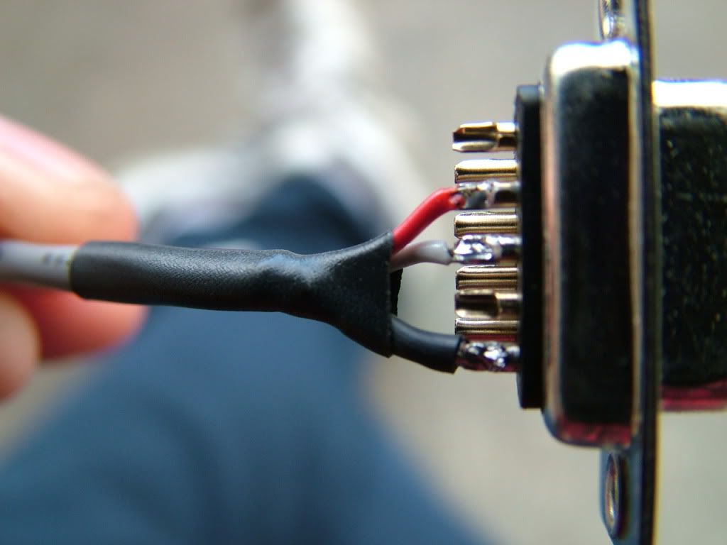
To make use of the reprogrammability, you would need a serial plug like the following:


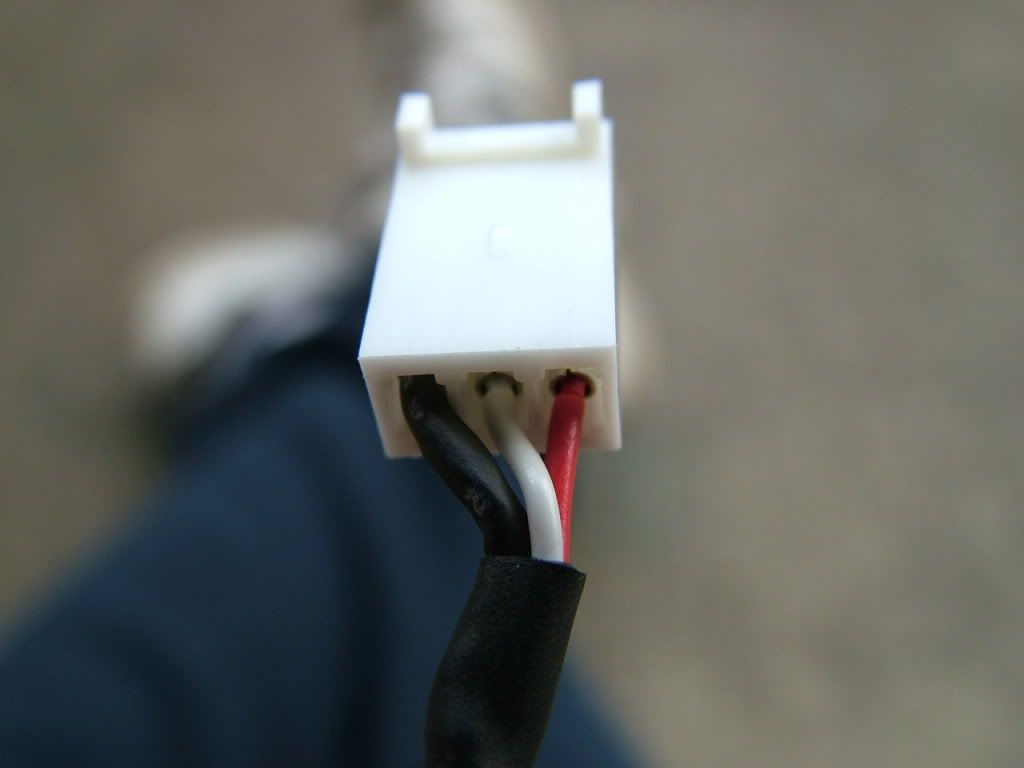
Here's how the other end should look (that goes into the control board):


It's easier just to solder the 3 wires right into the control board though. I think the serial plug thing (it probably should be female) is maybe $0.50 or so at an electronics store. It's really annoying soldering the stupid wires onto those little soder cups. It's easiest to first fill up those little cups on the serial plug, and then push the wire onto the solder. Then the wire melts right onto the little cup.

It might be around the 25th of this month before we get it mailed out. (payday hehe)
__________________
kits and boards
  Reply With Quote
Old 10-18-2009, 09:42 PM   #2454 (permalink)
EcoModding Apprentice
 
apowers's Avatar
 
Join Date: Aug 2009
Location: Tn
Posts: 126
Thanks: 14
Thanked 19 Times in 16 Posts
Hi Paul
I guess I don't need one now. On the next one will be fine. Right now I'm
just not getting any range at all. I did make a Bonn charger and it works great.
So I can plug in for a little juice just about anywhere. The problem is probably
that big old motor and the small 115ah batteries and all that wieght and the old
drive train dragging and you get picture. But still it is alot fun. You know on my
ammeter it never goes above 200 that may be all there is. I don't have any input
on the radio interferance because I never hooked it up.
Thanks
Alvin
  Reply With Quote
Old 10-18-2009, 10:05 PM   #2455 (permalink)
PaulH
 
MPaulHolmes's Avatar
 
Join Date: Feb 2008
Location: Maricopa, AZ (sort of. Actually outside of town)
Posts: 3,832

Michael's Electric Beetle - '71 Volkswagen Superbeetle 500000
Thanks: 1,368
Thanked 1,202 Times in 765 Posts
Hi Alvin! I'm not sure about the cause of the amps being around 200. I think it's related to Joe's code which was intended to be run at 144v. I'm going to mail you a new chip with current proportional to throttle. Assuming your batteries can take it, it will increase the PWM duty to whatever it needs to be so that it will use 0 amps at 0 throttle, and about 505 amps at 100% throttle. You will need to twist the little variable resistor that's on the control board a bit clockwise to keep the hardware overcurrent protection from coming on. How much???!!! Let's figure this out right now... Fully counterclockwise means about 490 amps for the hardware overcurrent to come on. Fully clockwise means about 775 amps. Twist it so that you get to around 550 or so. That would be about 60/285 of the full range of motion. So don't turn it toooooo far, but it probably wouldn't matter. hehe
__________________
kits and boards

Last edited by MPaulHolmes; 10-18-2009 at 10:26 PM..
  Reply With Quote
Old 10-19-2009, 01:08 PM   #2456 (permalink)
Master EcoModder
 
jackbauer's Avatar
 
Join Date: Sep 2009
Location: Ireland
Posts: 734
Thanks: 26
Thanked 304 Times in 171 Posts
I made some changes to the layout of the power section today. Fitted larger caps directly to the busbars and moved to the workshop to try the "warp13" motor. The following takes place between 5pm and 6pm:
  Reply With Quote
Old 10-19-2009, 02:01 PM   #2457 (permalink)
PaulH
 
MPaulHolmes's Avatar
 
Join Date: Feb 2008
Location: Maricopa, AZ (sort of. Actually outside of town)
Posts: 3,832

Michael's Electric Beetle - '71 Volkswagen Superbeetle 500000
Thanks: 1,368
Thanked 1,202 Times in 765 Posts
Awesome, Jack! There is very heavy filtering of the pwm signal right now in the software. Also, transitioning the variables from 8 0 to to 16 8 to 24 16 to ... to 128 120 (like you have it in the video) makes it transition from "throttle proportional to current" to "throttle proportional to pwm".

So, with throttle proportional to pwm, but with pwm is very heavily filtered, I think that's where you get the wild transitions for pwm.

Right now, it's a weighted average, so that the new value of pwm is taken to be:

pwmAverage = (127*pwmAverage + pwm)/128. So, it takes some time for pwm to have an affect on the average.
__________________
kits and boards
  Reply With Quote
Old 10-19-2009, 03:33 PM   #2458 (permalink)
Master EcoModder
 
jackbauer's Avatar
 
Join Date: Sep 2009
Location: Ireland
Posts: 734
Thanks: 26
Thanked 304 Times in 171 Posts
Can't wait to get the lem setup. That should make a difference. So far the igbts seem to be behaving fine. Granted its not really stressing them just running an unloaded motor. I think i'm gonna go with one 800amp device as the switch and one as the freewheel. See how it behaves. Should the lem be on the battery or motor side?

Its very impressive the degree of control available. I wonder could we design in a means to monitor motor rpm? I'm looking at making a simple circuit with a 12f pic to kill the pwm if the motor hits a certain rpm.
  Reply With Quote
Old 10-19-2009, 04:45 PM   #2459 (permalink)
PaulH
 
MPaulHolmes's Avatar
 
Join Date: Feb 2008
Location: Maricopa, AZ (sort of. Actually outside of town)
Posts: 3,832

Michael's Electric Beetle - '71 Volkswagen Superbeetle 500000
Thanks: 1,368
Thanked 1,202 Times in 765 Posts
LEM should be on motor side.

Oh, I think the pwm signal goes all over the place because it keeps over correcting because of the weighted averaging.
__________________
kits and boards
  Reply With Quote
The Following User Says Thank You to MPaulHolmes For This Useful Post:
jackbauer (10-19-2009)
Old 10-19-2009, 04:57 PM   #2460 (permalink)
Master EcoModder
 
jackbauer's Avatar
 
Join Date: Sep 2009
Location: Ireland
Posts: 734
Thanks: 26
Thanked 304 Times in 171 Posts
ah. I had it on battery side. doh! so could we try slightly different values?

  Reply With Quote
Reply  Post New Thread


Similar Threads
Thread Thread Starter Forum Replies Last Post
Paul and Sabrina's Cheap 3 Phase Inverter (AC Controller) with Field Oriented Control MPaulHolmes Fossil Fuel Free 3480 05-04-2022 05:43 PM
Paul & Sabrina's Cheap EV Conversion MPaulHolmes Fossil Fuel Free 542 11-12-2016 09:09 PM
Three Dirt Cheap DIY Electric Cars - Part 5 SVOboy EcoModder Blog Discussion 0 12-12-2008 04:10 PM


Powered by vBulletin® Version 3.8.11
Copyright ©2000 - 2024, vBulletin Solutions Inc.
Content Relevant URLs by vBSEO 3.5.2
All content copyright EcoModder.com