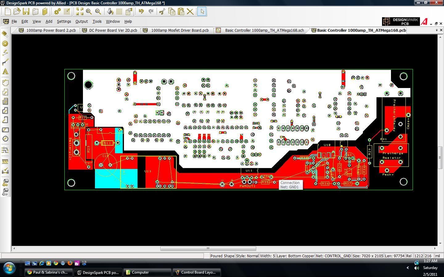
Does anyone want to see why I post things at 2 am?! I just took this picture 1 minute ago:

OK. Here's some stuff to check... My only concern here is in between the diodes, but I'm going to add some serious copper between the diodes. I could just have the diodes be surface mounted like they are now, but that increases the stray inductance and magnitude of spikes:
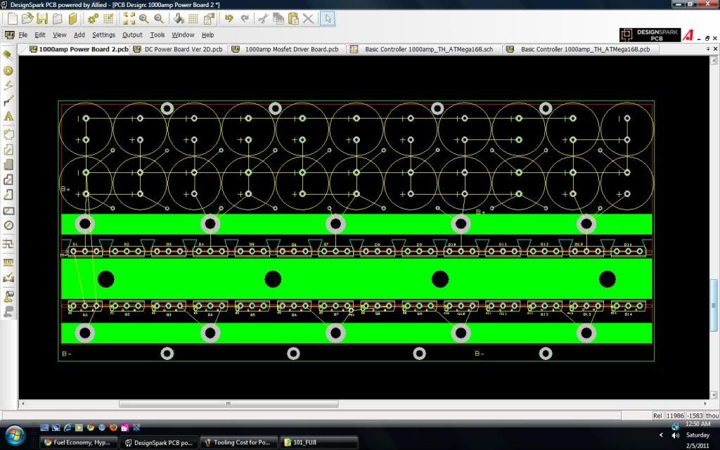
Also, having it be thru-hole diodes could increase the noise the control board sees? But I don't think that will be much of a problem. Stupid trade-offs. Makes me mad.
The 3/8"x3/4" B+ and B- bus bars are mounted so that the 3/8" side makes contact with the board. That cut a good chunk out of the loop.
Another concern I have: The surface mount current sensor has a less than 8uS response time, whereas the LEM had a less than 3uS response time. With a nicely tuned PI loop, the current should be kept under control, so I'm not too worried, but just something to think about.
I just checked the schematic, and I am very very very sure there aren't mistakes. hahaha.
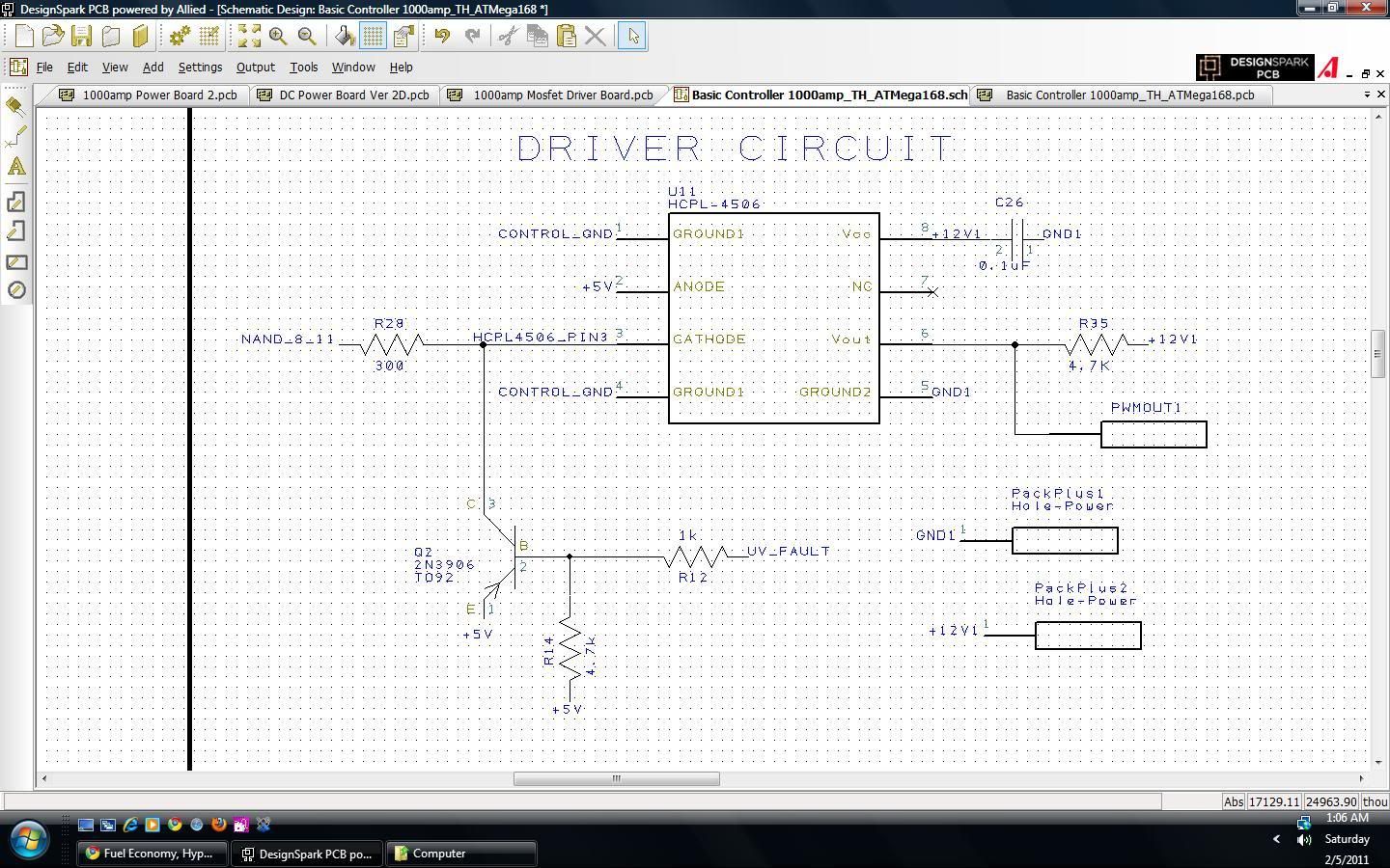
Here's the optocoupler part:
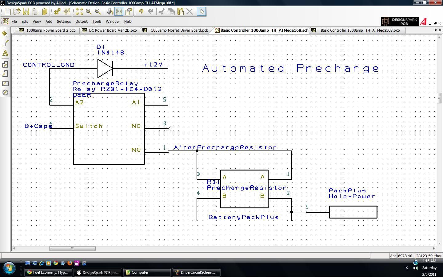
Here's the automatic precharge part. The relay just wastes about 30mA while you are driving, which saved the use of a pin on the microcontroller, and a couple dollars in components, and routing where there wasn't much room. Is it a problem to use a 1N4148 diode for the relatively puny coil to protect against inductive kick when the coil gets turned off? I read about it today and the consensus on the web seemed to be that it's fine for a 30mA 12v coil.
Here's the control board layout. The scale is 7.470" x 2.6". Relay, and high voltage stuff on the right side. There are a few extra holes so as to make the board compatible with Mr. Bighs IGBT board:
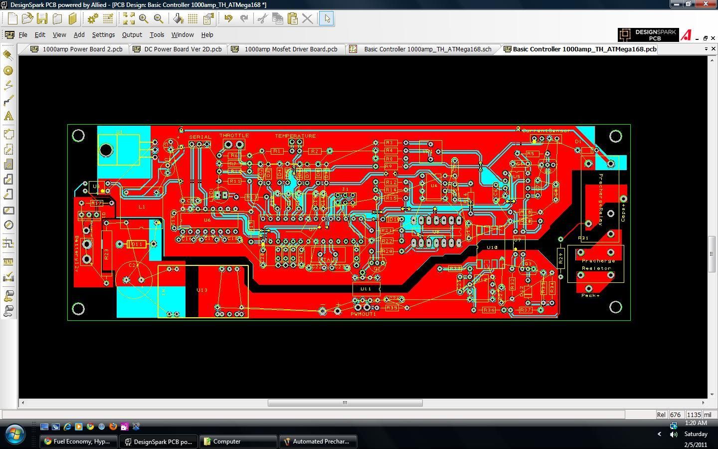
Here's the control ground plane in white. As unbroken as I could make it, since I think that helps with noise immunity.
