 01-18-2011, 08:42 AM
|
#4231 (permalink)
|
|
EcoModding Noob
Join Date: Dec 2010
Location: Raleigh, NC, USA
Posts: 24
Thanks: 9
Thanked 4 Times in 3 Posts
|
Quote:
Paul wrote:
"It will go from 0 pwm to 100% of pwm very quickly (maybe 1 or 2 seconds?) because it will try to make the current match the throttle. Like 5% throttle will try to command 5% of 500 amps, but no amps will be there, so it will ramp pwm all the way up to 100%. By the way, you tricked it!"
|
Doh! The board is too smart for me.
I think I have to get a proper probe for my silly-scope. I got it off eBay and it didn't come with a probe so I'm just using flying leads now.
What do you think the RS232 communication would look like running along with a 2.5V current sensor signal and 0 ohms on the pot? I may try to get the RTD explorer running to see ....
|
|
|

|
 Today Today
|
|
|
|
 Other popular topics in this forum...
|
|
|
|
|
01-19-2011, 02:08 PM
|
#4232 (permalink)
|
|
Master EcoModder
Join Date: Sep 2009
Location: Ireland
Posts: 734
Thanks: 26
Thanked 304 Times in 171 Posts
|
Today i connected the car's tacho sender to the controller via 2k2 resistor and 5v1 zener. Fran kindly put together some code last year for measuring rpm and this was the first test in vehicle. Works very well indeed. Now i just need to implement rpm limiting and motor idle for a future project.
Regards an igbt driver , I have a few modules that i used for a work related project that might be of interest. Datasheet:
http://www.evbmw.com/MT24.pdf
I am planning to do some experiments involving a revolt control board , mt25 driver , some 5th gen 1200v 600amp igbts and 4700uf 450v caps 
..........oh and really , really , really big heatsink!
edit: thinking of calling it revoliton 0.9 on the grounds the hass 300 can only go to 900amps 
__________________
Now, Cole, when you shift the gear and that little needle on the ammeter goes into the red and reads 2000 Amps, that's bad.
www.evbmw.com
|
|
|
|
|
The Following User Says Thank You to jackbauer For This Useful Post:
|
|
|
01-19-2011, 04:34 PM
|
#4233 (permalink)
|
|
EcoModding Noob
Join Date: Dec 2010
Location: Raleigh, NC, USA
Posts: 24
Thanks: 9
Thanked 4 Times in 3 Posts
|
Yeah! RS232 is working. I de-soldered the 0.1 uFs and soldered in the 1.0 uFs (MAX232).
Looks exactly like you described - as soon as the throttle moves off 0 Ohms, the PWM ramps up to full throttle very quickly (because of the steady "faked" signal from the current sensor of zero amps) - and stays there until the throttle returns to zero ohms.
One could imagine a very bizarre situation where a current sensor failed, but gave a nice steady 'zero amps' (2.5V) signal to the controller. Then, if the throttle were touched a little, off you go - full speed. Doesn't seem a very likely failure mode, though.
Michael
|
|
|
|
|
01-20-2011, 03:42 AM
|
#4234 (permalink)
|
|
EcoModding Apprentice
Join Date: May 2009
Location: Australia
Posts: 109
Thanks: 0
Thanked 2 Times in 2 Posts
|
Failure mode
I think Michael has stumbled on a failure mode that should definitely be reviewed. Needs to be some limit to current ramp. Something like
if PWM is increased and no current increase is measured then there is a problem
|
|
|
|
|
01-20-2011, 04:05 AM
|
#4235 (permalink)
|
|
PaulH
Join Date: Feb 2008
Location: Maricopa, AZ (sort of. Actually outside of town)
Posts: 3,832
Thanks: 1,362
Thanked 1,202 Times in 765 Posts
|
Exactly squiggles. A guy on here from the frozen north had a similar issue happen. The pedal contactor engaged after there was already some throttle. It could even be as simple as if pwm > x and current < y, then FAULT. I was hesitant to add it though, because I wasn't sure about a situation like very high revs down a hill or something. Couldn't it happen that pwm is very high, and the current is very small under healthy conditions? Just when the rpm is sufficiently low would it be a problem?
Hey DJ Becker! I was just thinking that because I'm limited to 3 and 4 ounce copper right now, that I shouldn't push too much current through too short of a board. I was thinking that 100 amps per leg was asking for trouble with the solder joints and the pcb tracks. I thought if I could just make the board a bit longer and use maybe 14 of the irfp4668's instead, which would keep the current down. Man, there are schottky 200v diodes in a TO-264 package that are rated for 250 amps. An almost perfect match to the TO-264 gigamos mosfets that are rated for 230amps. My main reason for doing SR before was because I couldn't find any diodes that matched the current of the mosfets.
|
|
|
|
|
01-20-2011, 04:26 AM
|
#4236 (permalink)
|
|
EcoModding Apprentice
Join Date: May 2009
Location: Australia
Posts: 109
Thanks: 0
Thanked 2 Times in 2 Posts
|
Paul, I agree that there may not be a fixed relationship between pedal position and PWM and current, although if your are going down hill fast you probably will not have your foot to the floor.
I can see that in most instances, if not all, when you increase (or decrease) pedal pressure you would expect a change in PWM and a corresponding change in current. The test would be to confirm there is a change rather than an absolute value......does that make sense?
|
|
|
|
|
01-20-2011, 04:31 AM
|
#4237 (permalink)
|
|
PaulH
Join Date: Feb 2008
Location: Maricopa, AZ (sort of. Actually outside of town)
Posts: 3,832
Thanks: 1,362
Thanked 1,202 Times in 765 Posts
|
Yes. Man, you australians keep really weird hours. I would just want to be really really really sure that a spurious event couldn't happen that would make a person think their controller was broken. That happened for a while when I had put in a "if throttle is way out of range for a single read, then FAULT". We spent forever tracking down a ghostly "latchup condition" that wasn't there.
|
|
|
|
|
01-20-2011, 04:37 AM
|
#4238 (permalink)
|
|
EcoModding Apprentice
Join Date: May 2009
Location: Australia
Posts: 109
Thanks: 0
Thanked 2 Times in 2 Posts
|
Yes, not good to rely on a single read. When I first got into microprocessor stuff (about 1980) two things became evident. You need to understand hysteresis so that you work within a range of values rather than at a single value and secondly even back then it was hard to visualise the speed at which a micro does it's calculations.....and no they are 10,000 times faster!!
|
|
|
|
|
01-20-2011, 04:46 AM
|
#4239 (permalink)
|
|
PaulH
Join Date: Feb 2008
Location: Maricopa, AZ (sort of. Actually outside of town)
Posts: 3,832
Thanks: 1,362
Thanked 1,202 Times in 765 Posts
|
Here's the driver board I'm planning on using. 2 drivers should be good for up to 20 mosfets, but I'm just going to try 14 for my prototype. That's about 71 or 72 amps per device for 1000 amps. I'm just hoping that it could do that for like 10 seconds. Enough to get up to speed in stop and go traffic, and do burnouts.
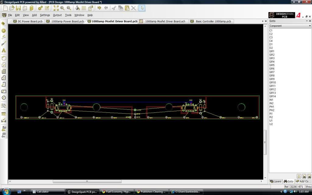
It doesn't matter as much to have the path from the optocoupler output to the driver inputs to be long. The 4 holes in the board are where the 4 mounting screws bolt it down. The board just sits right on top of the steel reenforcing thing, and the control board will be just above that. The 1000amp standard (non SR) control board, with the driver section removed, and converted to surface mount is done, and the power section is done too. I wish I had a million dollars. The driver board for example is only $0.25 each in quantities of like 5000. haha. But they would biodegrade by the time 5000 people got one.
I was planning on trying 1/2" x 1/2" bus bars for B+ and B- and 1/4" x 1" bus bar for M- bar. Same cross sectional area, but does the cross sectional perimeter matter more if the electrons run on the surface? I don't know how it works. I was thinking I could drill and tap the end of a 1/2"x1/2" bus bar to give better contact. I was just considering 1/2"x1/2" because it can take a sizeable chunk out of the length of the path that needs to be as short as possible.
Last edited by MPaulHolmes; 01-20-2011 at 11:54 AM..
|
|
|
|
|
The Following User Says Thank You to MPaulHolmes For This Useful Post:
|
|
|
01-20-2011, 10:36 AM
|
#4240 (permalink)
|
|
ReVolt Enthusiast
Join Date: Jun 2009
Location: Michigan, USA
Posts: 239
Thanks: 97
Thanked 47 Times in 40 Posts
|
Quote:
Originally Posted by MPaulHolmes

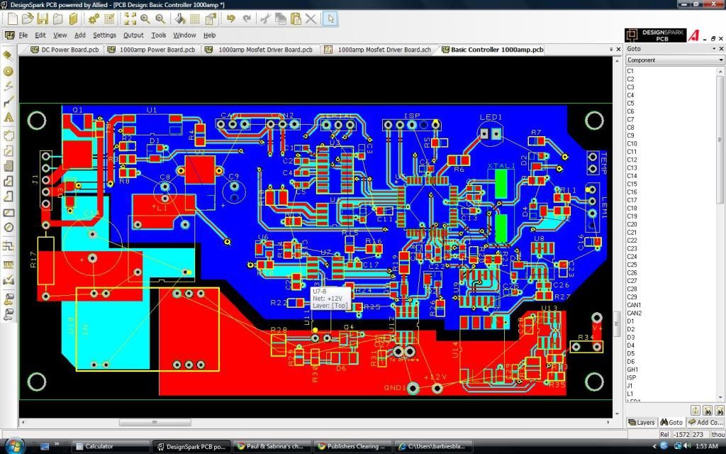
The 1000amp standard (non SR) control board, with the driver section removed, and converted to surface mount is done, and the power section is done too.
|
Hi Paul,
Thanks for showing us your progress on the 1000 Amp ReVolt controller !!!
I was looking at your SMT Controller image and wondered, is it still using a ATMEGA or DSPIC processor ??? I also noticed CAN1 & CAN2 ports ???
Could you share some more info on it's specs ???
The timing of your 1K ReVolt is ironic, I am part of a college team that is evaluating a 1K Zilla, and a 1K Soliton Controller right now for a new EV project.
Thanks,
-Mark
|
|
|
|
|


