 06-02-2018, 12:32 PM
|
#721 (permalink)
|
|
Master EcoModder
Join Date: Jan 2008
Location: Sanger,Texas,U.S.A.
Posts: 16,489
Thanks: 24,515
Thanked 7,436 Times in 4,817 Posts
|
22-degrees
Quote:
Originally Posted by Tesla

I have re-done the equation with the specs from post 517 (3-Wheeler) just to explore those specs further, although it does come up with a 2.5:1 Aspect ratio, there are other issues which make it less than ideal.
I have made the x & y grid lines the same as the template so it's just a matter of lining up the height and length markers to compare, the overlay is below:
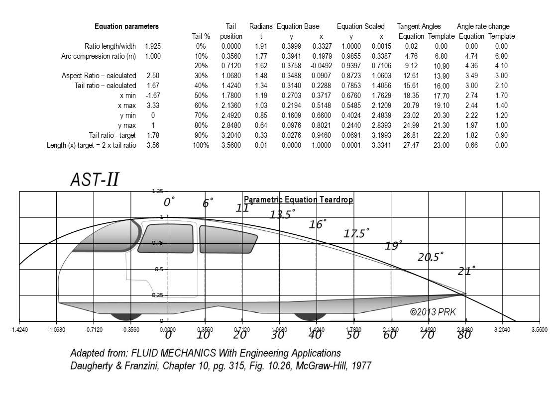
I think there's probably enough detail in the overlay to explain itself, particularly comparing the angles which start gentle but then accelerate to 27 degrees at the 80% mark, which breaks the 22 degree rule. Although the Aspect ratio is 2.5:1, the issue is that 1/3rd was in the fore body, which leaves the tail with a 1.67 tail ratio. |
In Hucho's book he shared a metric researched by Buchheim et al.,in which they reported that we could take the rear down-slope to a maximum 23-degrees without inviting flow separation.
Buchheim's lowest drag body was the VW 'Flow',at Cd o.14 as a long tail.
If you look at his graphic for this car,I came up with 22.5-degrees maximum angle by just laying a protractor to the drawing.
So it looks like we get a little wiggle room without degrading performance.
Again,great work! Thanks so much! 
__________________
Photobucket album: http://s1271.photobucket.com/albums/jj622/aerohead2/
|
|
|

|
 Today Today
|
|
|
|
 Other popular topics in this forum...
|
|
|
|
 06-11-2018, 08:20 PM
|
#722 (permalink)
|
|
Master EcoModder
Join Date: Feb 2012
Location: Australia
Posts: 355
Thanks: 5
Thanked 76 Times in 50 Posts
|
Quote:
Originally Posted by aerohead

In Hucho's book he shared a metric researched by Buchheim et al.,in which they reported that we could take the rear down-slope to a maximum 23-degrees without inviting flow separation.
Buchheim's lowest drag body was the VW 'Flow',at Cd o.14 as a long tail.
If you look at his graphic for this car,I came up with 22.5-degrees maximum angle by just laying a protractor to the drawing.
|
So then I assume if we design the curve to 23 degrees to depart the body at the 80% mark that would be within the parameters and this would also mean that the overall principle would likely be less than the std 1.78 tail ratio. |
|
|

|
|
The Following User Says Thank You to Tesla For This Useful Post:
|
|
 06-11-2018, 09:27 PM
|
#723 (permalink)
|
|
Master EcoModder
Join Date: Feb 2012
Location: Australia
Posts: 355
Thanks: 5
Thanked 76 Times in 50 Posts
|
Template power equation
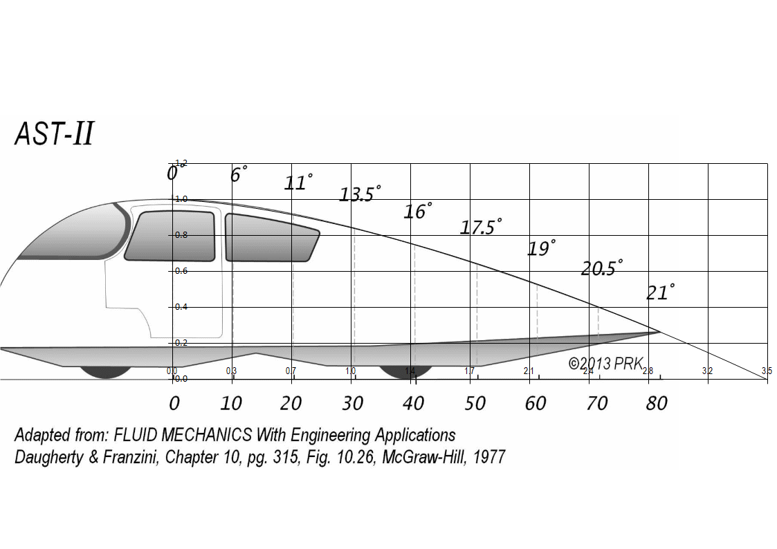
When I was reviewing some of the equations I've posted I noticed some anomalies with the Angles Rate of change from segment to segment, this would be the acceleration of inclination. Even though the curve itself may look ok, when you chart the rate of change it shows an irregular pattern, just like a hill may appear to have a smooth contour from a distance but is full of ups & downs when you walk it. This is a bit of an acid test, but I figure we may as well try to start closer to perfection knowing that the errors will only multiply in the build stage. Just as an example I charted some of the original template angles, I did original charts in colour, but forgot and saved pics in B&W, so a bit harder to trace lines, but I'm sure you'll get the idea:
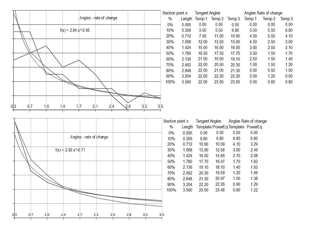
The wildest line on the first chart is the original template angles, the next zagging one was the re-measurements off the AS-II template and the most consistent is the current template angles, the 6.8 to 23 degrees. I included a trend line for the current template plot which is the fine curved line in there and the equation on the chart is for the trend line. So going to the next stage I started playing with the template angles so basically trying to keep the start at 6.8 and end at 23 whilst getting the centre to conform to a continuous curve and the second chart shows that progression, although to attain a fall of 1 in 3.56 the depature angle was 23.48 degrees at the 100% mark. I used straight line charting as the smooth line can be deceptive when there are very few plot points.
Then to fine tune, I made a table in 1% increments and charted those points:
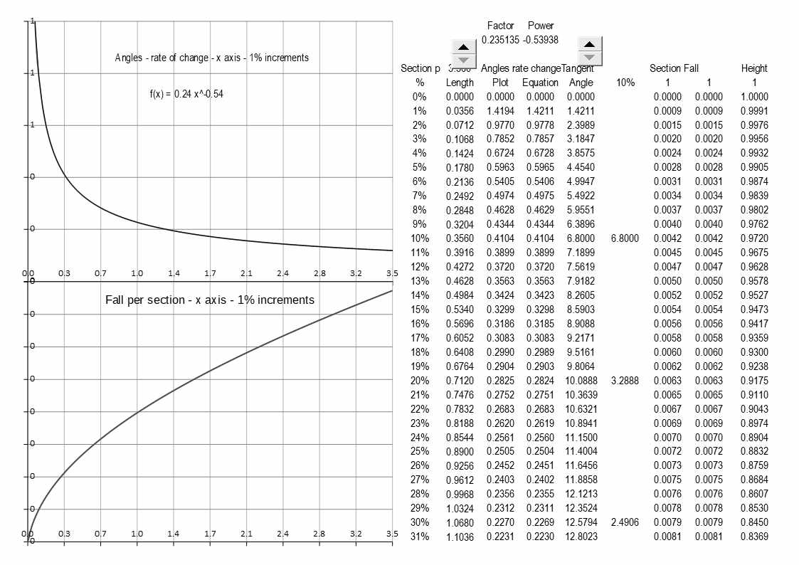
The first chart is the progressive angle change and the lower chart is the actual fall per section calculated from those angles, and there is a snapshot of the first part of the table, as there are only two variables and just multiplication the curve can only be continuous unlike polynomial equations. There is a limited range of options whilst trying to work within "what we believe the constraints to be", for example is 6.8 degrees the max at the 10% mark or could one go higher?
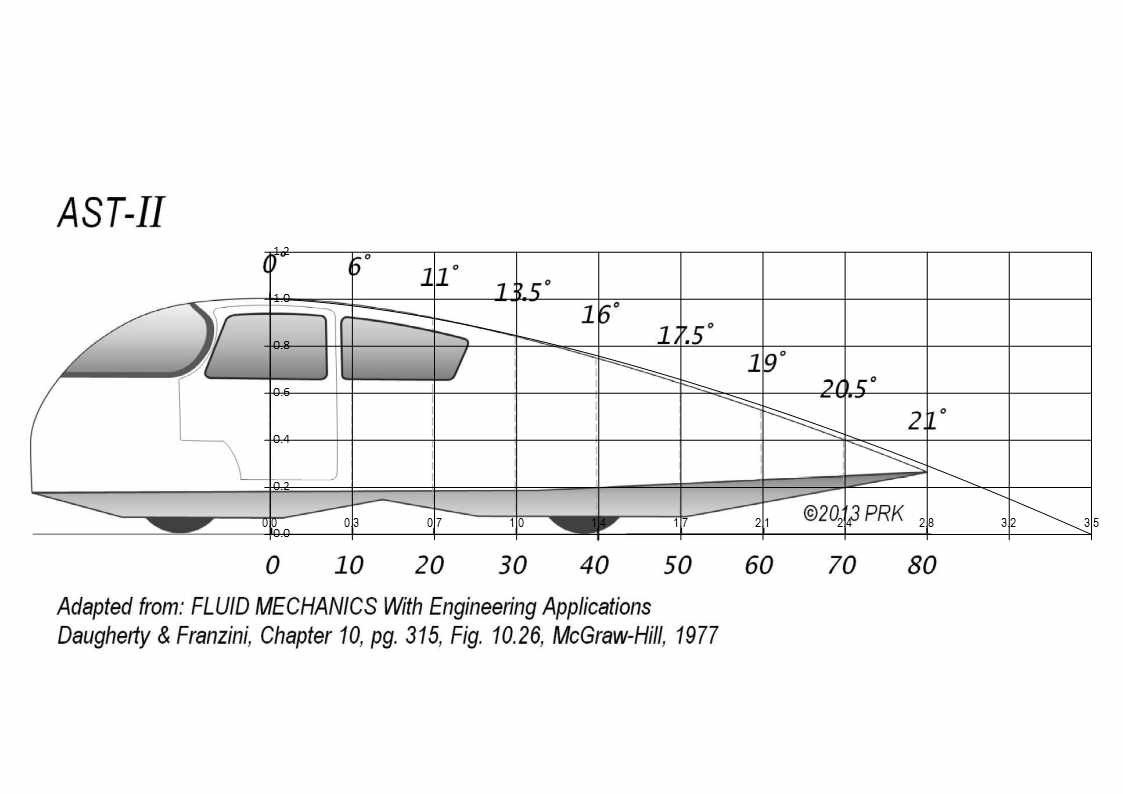
The example shown is 6.8 -23.48 degrees with a 1.78 tail ratio, with the template overlay below I have just lined up the section markers so you see the template image must be accelerating at a greater rate than the angles specified, but we are talking in the decimals here, just for comparison I also did an overlay compressing the curve so it matched template, but this puts the section markers closer together, both images posted below.
No matter how you flip it the match is pretty good and I like the fact of a smooth angle progression.
 |
|
|

|
|
The Following 2 Users Say Thank You to Tesla For This Useful Post:
|
|
 06-11-2018, 09:34 PM
|
#724 (permalink)
|
|
Master EcoModder
Join Date: Aug 2012
Location: northwest of normal
Posts: 29,315
Thanks: 8,337
Thanked 9,097 Times in 7,514 Posts
|
I think The Template is ideal in theory only, but I will ask: Do you think the disparity from 30 to 50% is more significant than what's at 80%? It certainly involves more cross-sectional area.
aerohead — Can you comment on 'phantom tail' truncations and the reflex curve add-on to the Baby Template? I forget, was it same-same with or without it?
Whoa! Simul-post. I'll have to go back and read that.
__________________
.
.Without freedom of speech we wouldn't know who all the idiots are. -- anonymous poster
___________________
.
.Impossible is just something we haven't done yet. -- Langley Outdoors Academy
|
|
|

|
|
The Following User Says Thank You to freebeard For This Useful Post:
|
|
 06-11-2018, 10:04 PM
|
#725 (permalink)
|
|
Master EcoModder
Join Date: Feb 2012
Location: Australia
Posts: 355
Thanks: 5
Thanked 76 Times in 50 Posts
|
Perfection
I've been pondering on this for a while now and I think we are coming to the limits of this process, as I understand it we have experimental data and experience which suggests a teardrop type shape with probably a bit less than the 2.5:1 ratio as being the ideal. The risk being that the penalties accrue much more rapidly below 2.5:1 than above if something goes awry. Then there is the real world where appendages change the story whether you are a fish, bird or motor vehicle.
Unless we can determine any other specific mathematical relationships, without extensive testing it is hard to determine what the ideal distribution along the curve would be.
My personal thoughts are that something of an S-curve might be the ideal where the angles accelerate rapidly through to 70-80% and then begin to taper back towards horizontal so that the converging air streams are aligned in a parallel manner. The Parametric equation had this characteristic, but any online search for teardrop equations will produce dozens of results, but which one is best?
|
|
|

|
|
The Following User Says Thank You to Tesla For This Useful Post:
|
|
 06-12-2018, 12:19 AM
|
#726 (permalink)
|
|
Master EcoModder
Join Date: Aug 2012
Location: northwest of normal
Posts: 29,315
Thanks: 8,337
Thanked 9,097 Times in 7,514 Posts
|
My personal thoughts turn to modelability. How accurately can you define the surface? The solution seems to be a octahedral-based geodesic structure.
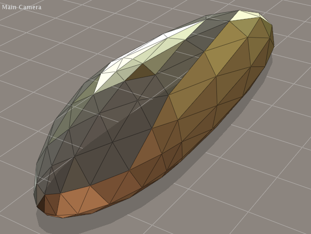
If you like I can show* the progression from a sphere, to a 30/70 front-rear split, cross-section that is prolated above the equator and oblated below and flat-bottomed, with an overall resemblance to a humped-backed Dymaxion.
This relies on a linear transformation fore and aft of 'center'. With added complexity you could have a non-linear transform produce a reflex curve and stinger tail. The handful of data points that define http://ecomodder.com/forum/showthrea...tml#post373749 the [un-mirrored] half shape can still be calculated to as many decimal point as you require.
Further transformation. I haven't found a way to apply this to the octahedral geodesic, but it could probably be done station-by-station. A squircle can be anywhere between a square and a circle.

This can resolve packaging issues, like windshield headers without upper corners, and etc. The subject is covered here:
http://ecomodder.com/forum/showthrea...ion-23333.html
edit:
* Permalink #29
__________________
.
.Without freedom of speech we wouldn't know who all the idiots are. -- anonymous poster
___________________
.
.Impossible is just something we haven't done yet. -- Langley Outdoors Academy
Last edited by freebeard; 06-12-2018 at 12:48 AM..
|
|
|

|
|
The Following User Says Thank You to freebeard For This Useful Post:
|
|
 06-12-2018, 02:49 AM
|
#727 (permalink)
|
|
Master EcoModder
Join Date: Feb 2012
Location: Australia
Posts: 355
Thanks: 5
Thanked 76 Times in 50 Posts
|
As for modelability, irrespective of how complex you make it, we can define it mathematically as a static form, but I think the issues lie more in practicality, both in interior functionality as well as exterior performance. The shapes that you seem to allude to are more along the lines of the old style streamline caravans with the rounded corners which performed brilliantly in managing as an appendage to the main vehicle, but not necessarily as the main vehicle with all the steering and braking controls fitted, the rounded shape does note bode well to parallel air streams but does increase stability in crosswinds where a phantom boat tail may well be disrupted.
Hence I think not much beats the robust handling Kammback that can handle a little disruption from crosswinds when 98% of it's life is spent toting a phantom tail, the gift that keeps on giving.
|
|
|

|
|
The Following User Says Thank You to Tesla For This Useful Post:
|
|
 06-12-2018, 08:45 AM
|
#728 (permalink)
|
|
Master EcoModder
Join Date: Jul 2011
Location: Ann Arbor, Michigan
Posts: 4,209
Thanks: 140
Thanked 2,824 Times in 1,981 Posts
|
Quote:
Originally Posted by Tesla

........... a phantom tail, the gift that keeps on giving.
|
If I read this correctly, good thoughts regarding cross winds.
This image below may help in visualization though it lacks the rounded C-pillars most of us would favor.
Forces and flow structures evolution on a car body in a sudden crosswind
https://www.sciencedirect.com/scienc...67610514000506

Quote:
|
Our analysis shows that the region which is most sensitive to crosswind is located at the rear part of the leeward flank. However, changes in the rear geometry (from squareback to fastback body) only affect the established lateral coefficients values while transient duration and the force overshoots appear not to be significantly modified. Furthermore, the circulation of the most energetic leeward vortex appears to be correlated with the lateral coefficients transient evolutions.
|
I could use a translation into Ecomodder English. 
__________________
George
Architect, Artist and Designer of Objects
2012 Infiniti G37X Coupe
1977 Porsche 911s Targa
1998 Chevy S-10 Pick-Up truck
1989 Scat II HP Hovercraft
You cannot sell aerodynamics in a can............
|
|
|

|
|
The Following User Says Thank You to kach22i For This Useful Post:
|
|
 06-12-2018, 10:57 AM
|
#729 (permalink)
|
|
Master EcoModder
Join Date: Aug 2012
Location: northwest of normal
Posts: 29,315
Thanks: 8,337
Thanked 9,097 Times in 7,514 Posts
|
Quote:
|
As for modelability, irrespective of how complex you make it, we can define it mathematically as a static form, but I think the issues lie more in practicality, both in interior functionality as well as exterior performance.
|
??? Complexity vs practicality? How about two dimensions vs three?
Quote:
|
I could use a translation into Ecomodder English.
|
"Gusting winds don't affect different body shapes differently. Furthermore, something something." Or something.
__________________
.
.Without freedom of speech we wouldn't know who all the idiots are. -- anonymous poster
___________________
.
.Impossible is just something we haven't done yet. -- Langley Outdoors Academy
|
|
|

|
 06-13-2018, 10:50 AM
|
#730 (permalink)
|
|
Master EcoModder
Join Date: Jan 2008
Location: Sanger,Texas,U.S.A.
Posts: 16,489
Thanks: 24,515
Thanked 7,436 Times in 4,817 Posts
|
likely be less
Quote:
Originally Posted by Tesla

So then I assume if we design the curve to 23 degrees to depart the body at the 80% mark that would be within the parameters and this would also mean that the overall principle would likely be less than the std 1.78 tail ratio.
|
I had a graphic for Buchheim's Cd 0.14,long-tail,VW Flow body that I generated from a nested diagram presented by Hucho.It was in my PhotoBucket account and I've lost the ability to share over 700 images.Sorry!
It would be the best 'explanation' for what Buchheim and his team came up with.
The '23' degree slope does imply that we could cheat on the length of the aft-body a smidge,but you'd want to have a look at the flow body before you passed judgement.
While Hucho also presented Mair's 22-degree 'solution' for attached flow,we could take 23-degrees as the absolute maximum slope (given a proper streamlined leading transition) which guarantees flow attachment.
Since members may invest in the neighborhood of 800-man-hours to create a streamlined fairing,I thought that 22-degees would be a safe insurance policy.
__________________
Photobucket album: http://s1271.photobucket.com/albums/jj622/aerohead2/
|
|
|

|
|