07-26-2013, 02:16 PM
|
#471 (permalink)
|
|
Master EcoModder
Join Date: Mar 2013
Location: Grand Rapids, MI
Posts: 838
Thanks: 1,380
Thanked 209 Times in 155 Posts
|
Dear Neil,
We all think this is an awesome project. Please don't compromise on materials.
|
|
|

|
|
The Following User Says Thank You to mikeyjd For This Useful Post:
|
|
 Today Today
|
|
|
|
 Other popular topics in this forum...
|
|
|
|
|
07-26-2013, 02:31 PM
|
#472 (permalink)
|
|
Master EcoModder
Join Date: May 2008
Location: Maynard, MA Eaarth
Posts: 7,908
Thanks: 3,475
Thanked 2,953 Times in 1,846 Posts
|
I am going to reinforce the attachment points for the suspension subframes, of course. They will be sleeved through to reinforcements on the back, and they will cradle the weight.
The bottom and the sides of the chassis form a giant 'U' channel and the continuous fiberglass surfaces on the outside and the inside, is going to be one of the stiffest structures imaginable. The only openings are the windows, so the entire side of the foam there is about 6" thick and this is orders of magnitude stronger than most other structures. There is a airplane with a composite sandwich fuselage that has just a 10mm thick foam core...
The longitudinal dividers in the battery bays will form ribs in the floor, and the 1" thick floor panels are going to be screwed into the chassis, strengthening it further. If needed, I can have long metal 'U' channels fabricated to "line" the center battery bays to act a long box beams in the floor.
With just the plywood subfloor I had inside, the chassis of foam alone was strong enough for my 245 pound self to be inside.
I've worked with epoxy glue and it is also somewhat bendable and it too softens up in the heat. So I don't think I am giving up on much strength - if any at all - by using Titebond III.
The glue is soaking into and adhering to the fiberglass very well indeed, and glass is 7X a strong as steel in tension. The glue is what I have been working with all along and it is a great match with this foam. The joints are far stronger than the foam itself.
Oh, I have used this glue with old cloth to make the rear wheel covers on my xA - I stretched the cloth over the plastic wheel covers, daubed on the Titebond III, and spray painted the outside only, and they have totally been fine through rain and snow and ice for almost a year, now.
I'm going to test these pieces and I will improve things as I go along, if needed. This is a malleable process.
I REALLY appreciate all of your concerns, and I am taking lots of advice from people on this forum and others, too. The roughened surface idea came from someone here on EM, and way back at the beginning of the process, I worked in the Smart ForTwo windshield (instead of a totally complex custom one that I had originally come up with) - and a whole lot of other smaller things along the way. ALL of those discussions were invaluable to me and this design; whether or not they get used.
One of the strongest suggestions I got from many people was to start with an existing car, and modify that - like what Dave Cloud did with his Dolphin. And I may still regret not going that route! But with my skill set, and the fact that I started with the 3D computer model (which is unusual, I think?) I am glad that I have done it the way I did.
I went back and forth several times between doing a composite sandwich and a tube steel chassis. In the end it came down to an excellent suggestion (probably from someone here on EM?) to get the Phlatboyz PhlatPrinter III kit - that made it possible to translate the virtual 3D model directly to a physical reality. So, at every step along the way over these past 3+ years I have been working on CarBEN EV5, I have been working through each and every challenge along the way. And working with this glue over the last year and half, I am confident that it will work with the fiberglass, too.
+++
The link that Galane posted on the three Titebond glues mentions that Titebond III is 4,000 PSI. And the Dow XPS foam is 25PSI - it is quite springy and quite strong right up until it pops.
How strong is epoxy? And what about typical white EPS or closed cell polyisocyanurate foams?
Last edited by NeilBlanchard; 07-26-2013 at 03:29 PM..
|
|
|
|
|
The Following User Says Thank You to NeilBlanchard For This Useful Post:
|
|
|
07-26-2013, 09:52 PM
|
#473 (permalink)
|
|
Master EcoModder
Join Date: Jul 2009
Location: idaho
Posts: 282
Thanks: 0
Thanked 96 Times in 74 Posts
|
How strong is epoxy? A lot stronger than any PVA glue. Some numbers for West Systems
WEST SYSTEM | Epoxy Resins and Hardeners - Physical Properties
It's not just about yield strength. Also check out the flexural strength, hardness, compression yield and the rest.
I've been looking and have yet to find any such numbers for Titebond III. Can it withstand the loads the suspension and other components will put on it without cold flowing?
Wood glues are designed for wood - fairly rigid and non-compressible. The glue holds the wood parts together. The wood and the shape of the glued joints are responsible for most of the strength. Some amount of flexibility keeps the glue from cracking when put under stress. If a piece of furniture is stressed enough for it to fail, it doesn't matter much whether it's the glue or the wood that breaks.
Resins designed for use with fibers in composites are made to not compress, creep, cold flow, flex too much or be too rigid. Putting it over a foam core, the foam adds strength much the way the gas in a blimp keeps the envelope from buckling. With no empty space inside, it takes quite a bit more stress to buckle a thin composite layer. Without the foam filling, the composite layer would need to be thicker to prevent buckling.
Coating your foam car body with glass fiber and wood glue may work for a while, but I wouldn't expect it to be usable long term. Given the much lower tensile strength and the other critical properties of the PVA that are unknown - that's just too much that's unknown to use a product in such an "off label" application where human safety is involved.
Contact the company that makes the glue and ask if they have any of the data like is on that epoxy chart.
Getting injured or dead because the body of your homebuilt vehicle breaks would really suck. |
|
|
|
|
The Following 2 Users Say Thank You to Galane For This Useful Post:
|
|
|
07-27-2013, 05:43 AM
|
#474 (permalink)
|
|
It's all about Diesel
Join Date: Oct 2012
Location: Porto Alegre, Rio Grande do Sul, Brazil
Posts: 13,032
Thanks: 0
Thanked 1,720 Times in 1,534 Posts
|
Quote:
Originally Posted by NeilBlanchard

I have used this glue with old cloth to make the rear wheel covers on my xA - I stretched the cloth over the plastic wheel covers, daubed on the Titebond III, and spray painted the outside only, and they have totally been fine through rain and snow and ice for almost a year, now.
|
Old cloth? Cotton-based cloth? Well, natural fibers might have a better performance with wood glue than synthetic ones, but I wouldn't trust wood glue with anything other than wood in a structural function anyways. |
|
|
|
|
07-27-2013, 09:47 AM
|
#475 (permalink)
|
|
Master EcoModder
Join Date: May 2008
Location: Maynard, MA Eaarth
Posts: 7,908
Thanks: 3,475
Thanked 2,953 Times in 1,846 Posts
|
On one side, I used an old flannel bedsheet, and the other side I used a paint rag that definitely had a significant synthetic fiber content. Both stick to the plastic (ABS?) wheel covers very well.
|
|
|
|
|
07-27-2013, 07:54 PM
|
#476 (permalink)
|
|
Master EcoModder
Join Date: Nov 2012
Location: San Diego, California
Posts: 982
Thanks: 271
Thanked 386 Times in 259 Posts
|
Have you run a cost analysis for this proceedure?
I share the concerns others have voiced.
It may be only a few hundred USD to properly create a stressed glass reinforced fiber (GRF) skin in comparison to a Titebond (aliphatic resin ) glue shell. A proper GRF shell will have a minimal amount of resin. Most of your costs should be in your fiber cloths.
I had the opportunity to run into pretty much the same choice you are making right now. It was over 2 decades ago when I was part of a team prototyping a medical imaging system that had a large structural GRF shell. The glass over foam is commonly used for structural prototypes. However, in this instance, the foam core came to us in high density styrene instead of the usual urethane RenFoam. Because of the tight deadlines ( we often work on drop dead orders ) obtaining sufficient epoxy wasn't an option. We had to use the polyester resins we had on hand. A quick call to the local Ace Hardware and we were on the phone with someone from Titebond who gave us a quick rundown on how to build a protective shell of their glue ( original formula ) along with some "gossamer" cloth of some undefined makeup that is used in decorative sets. A light sanding once it had dried in the "hot room" and we were happily glassing away with the polyester we normally used. Metal backing plates and compression bolt tubes allowed us to hang the heavy radiation source and motors along with the patient bed and controls. The prototype was in operation for almost a year with no shell structure failures.
I do not know what the properties are for Titebond II and III but I assume it is much the same for the Original formula. The representative reminded us that the aliphatic resin glue has a creep strength ( cold flow or plastic flow under long periods of stress ) that are far below its ultimate tensile strength and yield stress. If the structure is to be under constant stress, he advised a safety factor of between 4-10 to take into account this creep. Temperature, humidity as well as the level of constant stress determine your level of safety factor.
I urge you to, at the least, consider the aliphatic resin glue as nothing more than a protective shell over your styrene foam core, then finish off with the normal polyester or epoxy if you feel you have to use it ( the PVA glue ). I would not worry about the use of the glue in the layer buildup of the foam as the core carries less stress flux than the shell. But, using the resin as a main part of your structure would mean a much thicker cross section to prevent the stress creep. You may inevitably lose your lightness and economy of construction.
|
|
|
|
|
07-28-2013, 12:13 AM
|
#477 (permalink)
|
|
EcoModding Lurker
Join Date: Sep 2010
Location: saint louis
Posts: 88
Thanks: 0
Thanked 4 Times in 3 Posts
|
that's another thing that seems odd to me, you could build the whole thing out of resin impregnated glass and keep it light but strong, proving the concept as well as possible, or you could use wood glue and a bunch of extra (and heavy) steel reinforcement.
with the resin, you can layer on all of your glass and impregnate it, then roll it out with the roller and if possible a wicking/absorbing material to aid in the process, and you would end up with an incredibly light, but strong structure.
|
|
|
|
|
07-28-2013, 01:37 PM
|
#478 (permalink)
|
|
Master EcoModder
Join Date: May 2008
Location: Maynard, MA Eaarth
Posts: 7,908
Thanks: 3,475
Thanked 2,953 Times in 1,846 Posts
|
I'm going to build a test jig so I can load the test samples consistently. It will be a 8' long 2x6 (or 2x4) that is reinforced with a wire and strut on the top to limit the bend in the wood. The composite sandwich samples will be supported on two "lines" underneath with short pieces of round closet pole stock that are 10" apart, and the weight will be loaded on a "line" with another piece of closet pole stock in the center of the top.
I'll start with the weight right on top of the center bearing, and then 1' out on the 2x, and then 2' then 3', etc. At the outer end of the 8' 2x, I'll have a wire "needle" that will indicate the deflection "amplified" by the length of the 2x arm, so small differences in deflection can be seen and quantified.
If this doesn't stress the samples enough, I'll go to a cantilevered setup.
Who wants to help me with the math? I will photograph the jig, and I can draft on the dimensions in DataCAD, and post that, along with the data.
|
|
|
|
|
07-29-2013, 07:57 PM
|
#479 (permalink)
|
|
Master EcoModder
Join Date: May 2008
Location: Maynard, MA Eaarth
Posts: 7,908
Thanks: 3,475
Thanked 2,953 Times in 1,846 Posts
|
Okay, here's my testing jig:
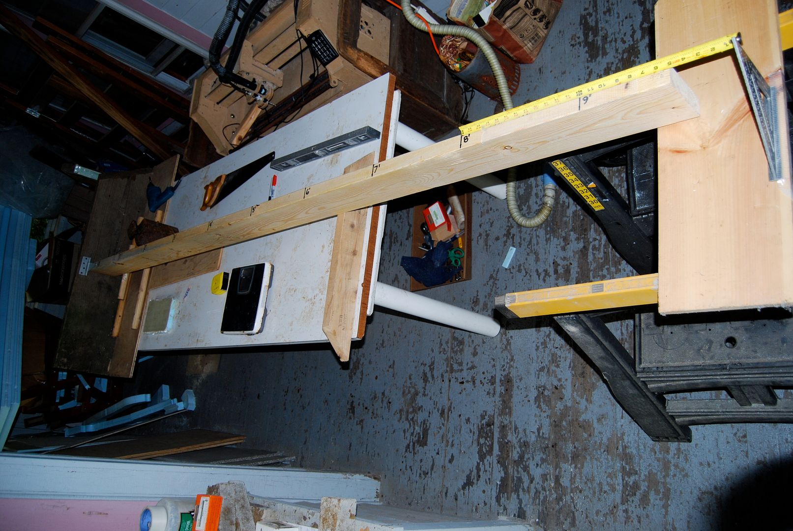 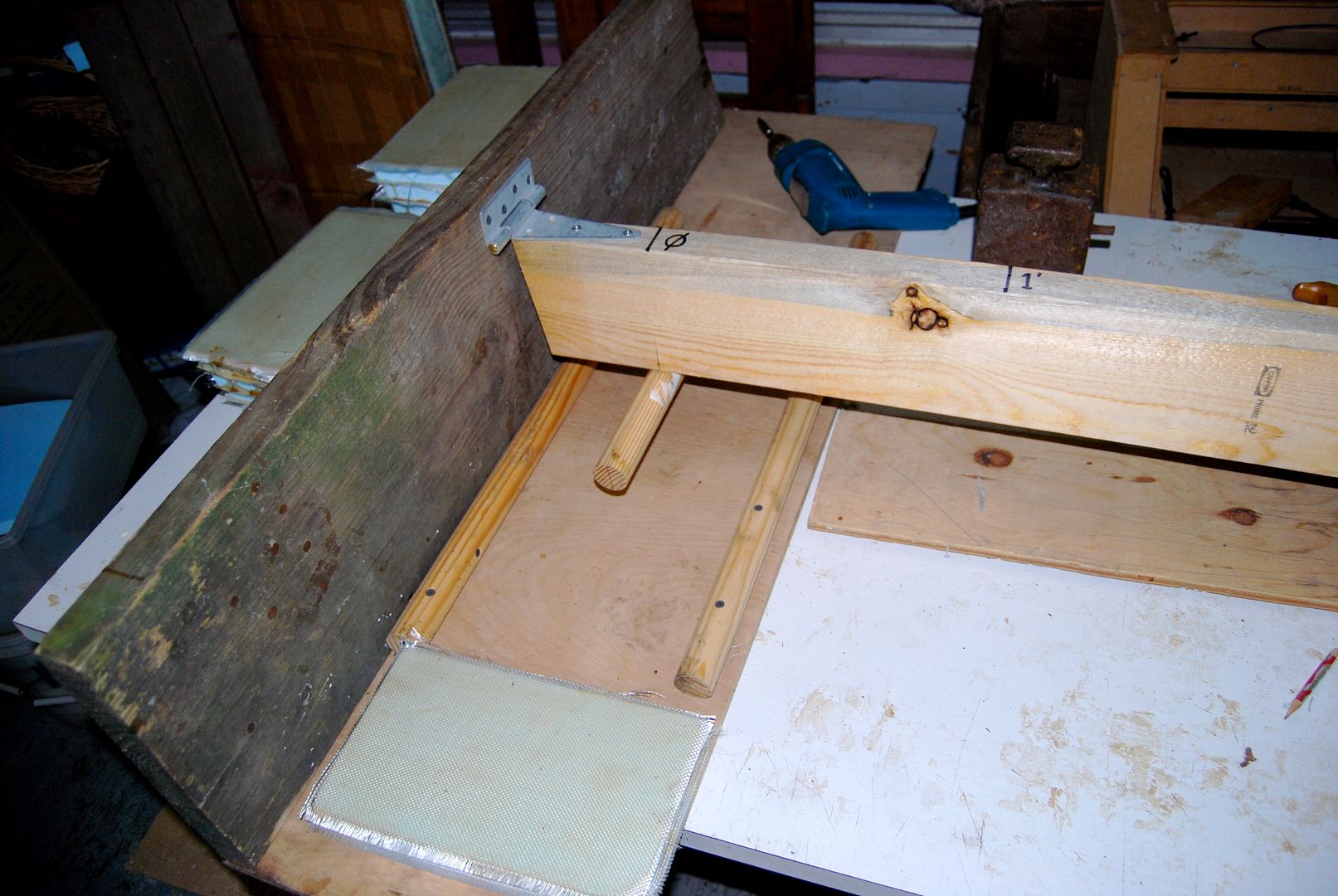 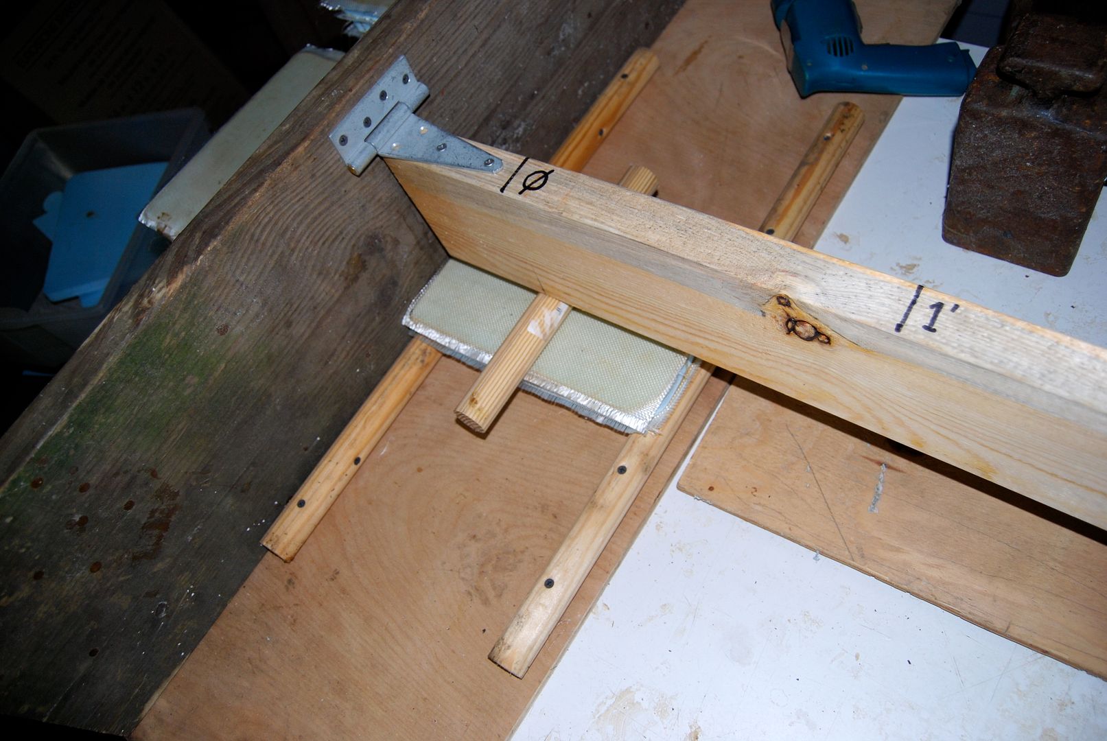 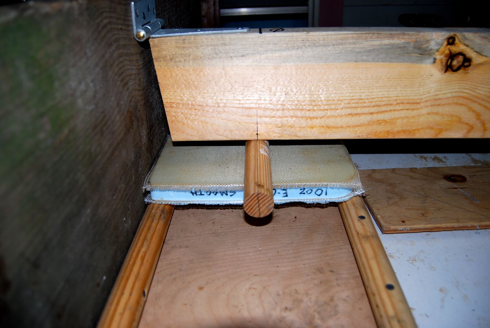 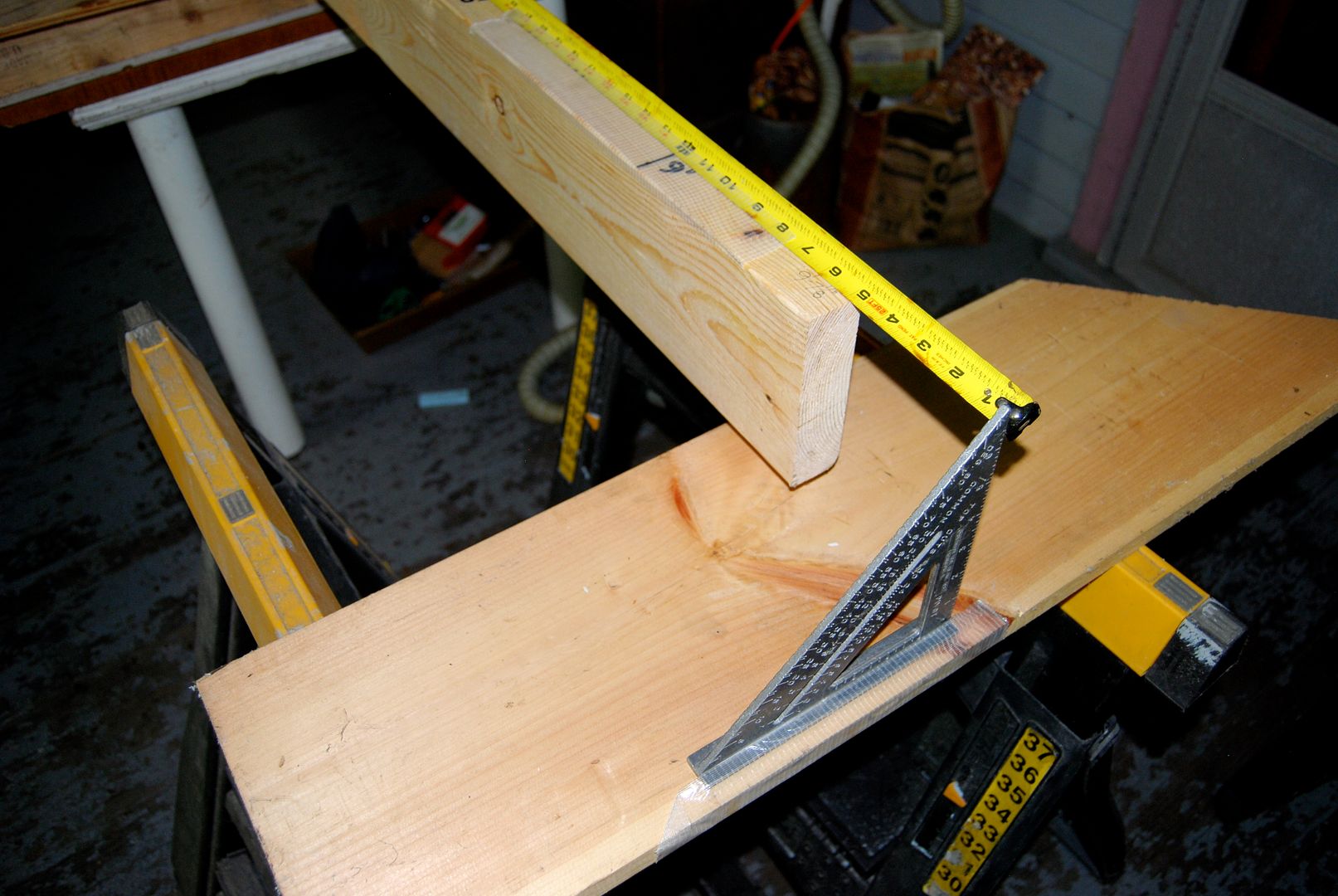
The 10' long 2x6 weighs ~19+ pounds. The three wood rods are 1 3/8" (1.375") diameter (closet poles) and the two supports are 10" apart, with the top bearing rod is in the middle; 5" from the two supports. The center line of the bearing rod is 5 11/16" (5.6875") from the hinge. The 2' piece of the steel tape extends to 10' from the bearing rod center line.
When I put the digital bathroom scale (only accurate to about 0.5 pound) under the free end of the 2x6 arm, it correctly indicates ~9.5 pounds, because half the weight is held up by the hinge. When I put the scale under the bearing rod, it indicates between 155-160 pounds.
[Correction: This is where it gets a bit more complicated - the ~6" on either side of the pressure rod weighs approximately 2 pounds and it acts "normally", and the 17+ pounds (the weight of the rest of the bearing rod to the free end) are acting like they are ~9' away (the distance to the free end), which works out to about 155 pounds, which is almost exactly what my bathroom scale indicates...
That would be ~25.8 pounds per linear inch across the 6" wide sample. ] When I add my 25.5 pound cast iron/lead filled weight at 1', 2', 3' etc. along the 2x6 arm the jig will be exerting some serious force on the samples. The (estimated) 900 pound battery pack that is about 7' long will come to "only" about 10.7 pounds per inch - and that is across about 4' span - 8X more material, at least.
I looked for @#$%&+! hours today for my large C-clamps and while *know* they are somewhere (I last used them last summer...) I'm gonna' go buy some new ones to anchor the jig at the pivot end, so I can actually use it.
But in the trial run, the 10oz E-glass sample deflects a lot, but it holds up well and springs right back. I strongly suspect I will need at least 2 layers of glass fabric, and maybe more to get the stiffness I need.
I will try to dimension the pictures, if that will help clarify things.
Last edited by NeilBlanchard; 07-30-2013 at 08:28 AM..
|
|
|
|
|
The Following User Says Thank You to NeilBlanchard For This Useful Post:
|
|
|
07-30-2013, 12:53 AM
|
#480 (permalink)
|
|
Master EcoModder
Join Date: Jul 2009
Location: idaho
Posts: 282
Thanks: 0
Thanked 96 Times in 74 Posts
|
Looks like a useful test rig to get a ballpark figure on what sort of force the different materials can withstand.
You know what'll happen when you bring those new clamps home. You'll walk into the shop and the first thing you see will be the old clamps. 
|
|
|
|
|
The Following 2 Users Say Thank You to Galane For This Useful Post:
|
|
|