 11-17-2022, 02:49 PM
|
#561 (permalink)
|
|
Master EcoModder
Join Date: Aug 2012
Location: northwest of normal
Posts: 29,301
Thanks: 8,334
Thanked 9,092 Times in 7,509 Posts
|
Quote:
|
Originally Posted by aerohead
5) Without CAD, you could fabricate a 'cardboard and duct tape' length of boat-tail capable of supporting attached flow, and by percentage, using either width or height, determine the 'size' of the new rear transom which would generate the desirable wake size.
|
What I did was use redwood strips and insert bulkheads at possible truncation locations.
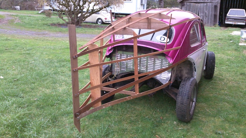
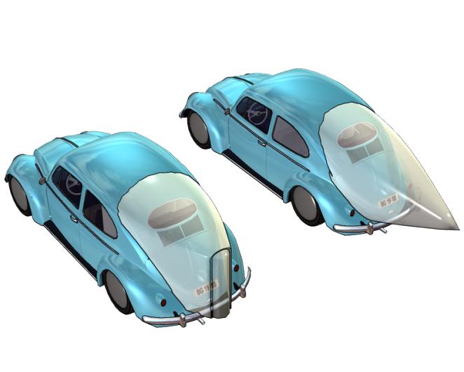
The hollow bulkhead is at the stock body length. The solid one at the end of a four-into-one header where there could be a stainless steel Coanda nozzle to energize the separation of the wake.
__________________
.
.Without freedom of speech we wouldn't know who all the idiots are. -- anonymous poster
___________________
.
.Impossible is just something we haven't done yet. -- Langley Outdoors Academy
|
|
|

|
 Today Today
|
|
|
|
 Other popular topics in this forum...
|
|
|
|
 11-17-2022, 03:07 PM
|
#562 (permalink)
|
|
Master EcoModder
Join Date: Jan 2008
Location: Sanger,Texas,U.S.A.
Posts: 16,477
Thanks: 24,502
Thanked 7,436 Times in 4,817 Posts
|
box-cavity
Quote:
Originally Posted by Phase

That’s what I was going to do. I was going to do a cardboard and duct tape box cavity 2 feet extension that follows the currently rear separation angles and then see how much smaller that wake size is
|
The perimeter of the 'box' must be exactly located, and look exactly like a 'mini-me' version of the original wake shape, with all its 'complications', and, exactly where a true boat-tail would terminate at 24-inches out. Every place where the outline 'turns' needs to be compartmentalized with a wall, in order to generate individual vortices which cannot contaminate each other ( simple, not easy ).
And no one can say what the performance of the 'box' will be compared to an actual tail.
The 2012 Coventry University modifications to the 1999 Audi A2 is the only semi-contemporary use of a box-cavity, and it's 'result' might inform any expectation as to performance.
Should be interesting! 
__________________
Photobucket album: http://s1271.photobucket.com/albums/jj622/aerohead2/
|
|
|

|
 11-17-2022, 04:54 PM
|
#563 (permalink)
|
|
Master EcoModder
Join Date: Aug 2012
Location: northwest of normal
Posts: 29,301
Thanks: 8,334
Thanked 9,092 Times in 7,509 Posts
|
My point was to go long to find the contour and then cut to size.
__________________
.
.Without freedom of speech we wouldn't know who all the idiots are. -- anonymous poster
___________________
.
.Impossible is just something we haven't done yet. -- Langley Outdoors Academy
|
|
|

|
|
The Following User Says Thank You to freebeard For This Useful Post:
|
|
 11-21-2022, 11:09 AM
|
#564 (permalink)
|
|
Master EcoModder
Join Date: Jan 2008
Location: Sanger,Texas,U.S.A.
Posts: 16,477
Thanks: 24,502
Thanked 7,436 Times in 4,817 Posts
|
'countour'
Quote:
Originally Posted by freebeard

My point was to go long to find the contour and then cut to size.
|
Technically, the rear fenders would have to be integrated into the aft-body extension, as Carl Breer did with the 1934 De Soto Airflow test mule.
An extremely complicated build, since body camber on the roof is the most 'mature', the main body plan-camber, in 'second-place', and the pontoon fenders just in their 'infancy.'
You'd want a bridge fiducial to keep track of all the evolving geometry, guarantee alignment, and side-to-side fidelity.
It would be the 'Tesla Model S of Beetles' though. Cd 0.244, vs Cd 0.495. 
__________________
Photobucket album: http://s1271.photobucket.com/albums/jj622/aerohead2/
|
|
|

|
 11-21-2022, 12:50 PM
|
#565 (permalink)
|
|
Master EcoModder
Join Date: Aug 2012
Location: northwest of normal
Posts: 29,301
Thanks: 8,334
Thanked 9,092 Times in 7,509 Posts
|
The concept ignored engine cooling and the rear fenders (basically everything from the beltline down).
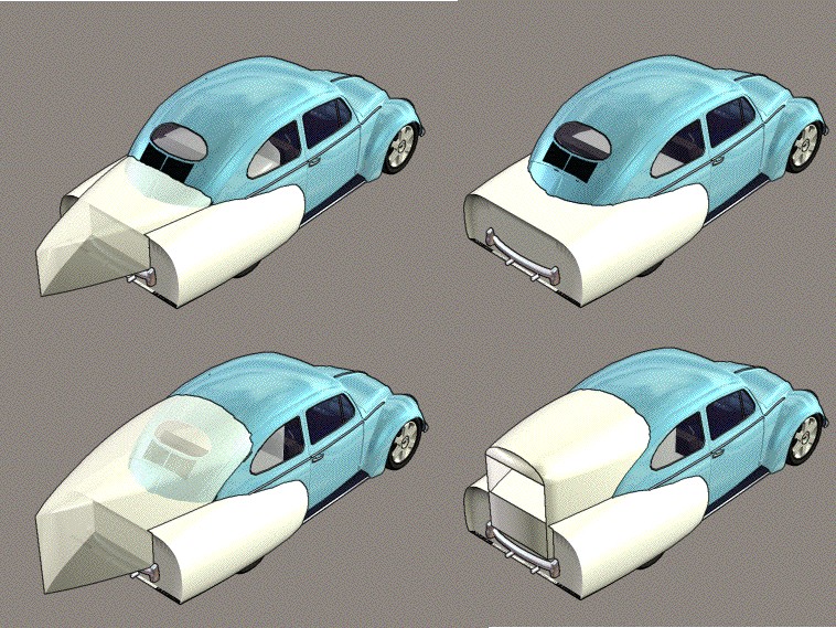
From the same time frame. I have better software now, but the computer's monitor died. My goal for today is to replace it (Nextstep has screens at half off -- 23-24" for $30).
Quote:
|
An extremely complicated build, since body camber on the roof is the most 'mature', the main body plan-camber, in 'second-place', and the pontoon fenders just in their 'infancy.'
|
This external duct dates to 2021:
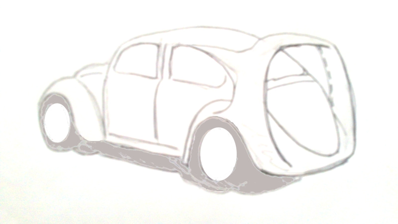
Basically, a truncated half-body with a gaping mouth that swallows the Beetle body wake. The dotted line on the rigfht indicates a coanda nozzle (like a Dyson fan). It was based on this:

[Phase: sorry about the thread jack]
__________________
.
.Without freedom of speech we wouldn't know who all the idiots are. -- anonymous poster
___________________
.
.Impossible is just something we haven't done yet. -- Langley Outdoors Academy
|
|
|

|
|
The Following User Says Thank You to freebeard For This Useful Post:
|
|
 11-21-2022, 01:20 PM
|
#566 (permalink)
|
|
Master EcoModder
Join Date: Jan 2008
Location: Sanger,Texas,U.S.A.
Posts: 16,477
Thanks: 24,502
Thanked 7,436 Times in 4,817 Posts
|
'swallows'
In order to reduce drag, it would have to be 'airtight' ( like the Airflow ), and it's cross-sectional area would have to diminish very gradually over it's length, in order not to produce an 'over-allowable' pressure increase. Other wise, the flow would separate, and it's game over.
Only non-ventilated cavities are capable of producing drag reduction.
__________________
Photobucket album: http://s1271.photobucket.com/albums/jj622/aerohead2/
|
|
|

|
 11-22-2022, 06:23 PM
|
#567 (permalink)
|
|
Master EcoModder
Join Date: Mar 2022
Location: oregon
Posts: 1,123
Thanks: 1
Thanked 595 Times in 472 Posts
|
Quote:
Originally Posted by aerohead

In order to reduce drag, it would have to be 'airtight' ( like the Airflow ), and it's cross-sectional area would have to diminish very gradually over it's length, in order not to produce an 'over-allowable' pressure increase. Other wise, the flow would separate, and it's game over.
Only non-ventilated cavities are capable of producing drag reduction.
|
define non ventilated cavities. what are your thoughts on the rear of the new prius? |
|
|

|
|
The Following User Says Thank You to Phase For This Useful Post:
|
|
 11-22-2022, 08:00 PM
|
#568 (permalink)
|
|
Master EcoModder
Join Date: Aug 2012
Location: northwest of normal
Posts: 29,301
Thanks: 8,334
Thanked 9,092 Times in 7,509 Posts
|
I'm curious as well.
Compare the VW GTI-650 to the drawing at #565.

Little or no added frontal area, with a converging duct to reduce the wake along an extended half-body configuration to maybe 50% the area?
__________________
.
.Without freedom of speech we wouldn't know who all the idiots are. -- anonymous poster
___________________
.
.Impossible is just something we haven't done yet. -- Langley Outdoors Academy
|
|
|

|
|
The Following User Says Thank You to freebeard For This Useful Post:
|
|
 11-23-2022, 12:16 PM
|
#569 (permalink)
|
|
Master EcoModder
Join Date: Jan 2008
Location: Sanger,Texas,U.S.A.
Posts: 16,477
Thanks: 24,502
Thanked 7,436 Times in 4,817 Posts
|
'non-ventilated'
Quote:
Originally Posted by Phase

define non ventilated cavities. what are your thoughts on the rear of the new prius?
|
Any boat-tail, or box-cavity must not allow any porosity/ aspiration / contamination to the very-vulnerable aft-body flow.
The surface must be air-tight, whether the skin of an actual tail, or each cell of a box-cavity.
If not, the existence of the voids induces an adverse pressure spike or gradient, triggering flow separation right then and there.
There's very little 'reason' for flow to remain attached to an aft-body.
Only the gentle reduction in cross-section of a 'streamlined' contour can allow the feeble flow to receive enough momentum interchange from the nearest streamline to prevent the air from just 'climbing' up the rear of the car, on it's way to the windshield header, where the pressure minimum occurs.
There exists, what Tamai refers to as a 'shape factor 'H'', which determines whether separation will occur. It requires CFD to work it.
Tamai comments, on page-62, ' The actual mechanism of turbulent separation and its reattachment is beyond the scope of this book.'
In the absence of a wind tunnel, or CFD, we're admonished to stick with rules-of-thumb regarding aft-body surface patch tangent angles. That's exactly what the ASTs are predicated upon.
Hucho had an associate write an entire chapter on boundary-layer theory in his 2nd-Edition, which does explain the mechanism for TBL separation.
Hucho, himself, studied under Professor Hermann Schlichting, who wrote the book, 'BOUNDARY-LAYER THEORY', which would be a reference requirement for any aerodynamicist ( I traveled to the University of Texas at Arlington, Texas, and photo-copied the entire book in their library, along with Fachsenfeld's.
__________________
Photobucket album: http://s1271.photobucket.com/albums/jj622/aerohead2/
Last edited by aerohead; 11-23-2022 at 12:24 PM..
Reason: typo
|
|
|

|
 11-23-2022, 12:21 PM
|
#570 (permalink)
|
|
Master EcoModder
Join Date: Jan 2008
Location: Sanger,Texas,U.S.A.
Posts: 16,477
Thanks: 24,502
Thanked 7,436 Times in 4,817 Posts
|
GTI-650
Quote:
Originally Posted by freebeard

I'm curious as well.
Compare the VW GTI-650 to the drawing at #565.

Little or no added frontal area, with a converging duct to reduce the wake along an extended half-body configuration to maybe 50% the area? |
I've no experience with any literature which demonstrated actual, real-world use, and the efficacy of such a structure, as regards to drag reduction.
__________________
Photobucket album: http://s1271.photobucket.com/albums/jj622/aerohead2/
|
|
|

|
|