 01-07-2015, 01:40 PM
|
#1531 (permalink)
|
|
EcoModding Apprentice
Join Date: Nov 2012
Location: East Midlands
Posts: 180
Thanks: 13
Thanked 81 Times in 52 Posts
|
Quote:
Originally Posted by P-hack

re: is 600 amps needed, yes, because it behaves much like a transformer, to get 288vdc @ 300 amps out, you need ~144vdc @ 600 amps in.
I goofed though, and used 60 amps in that example, fixed:/
Anyway, to keep the inductor the same (40uh) at 20khz, you can reduce the ripple by 1/2 to %15, or you can reduce the current by 1/2 (300A).
|
The peak inductor current would effectively be 600A (50% duty) but the average current would be about 300A. and even that would only be sustained for a few seconds. So I don't think for a traction application there's a need for an inductor rated at 600 continuous amps, as long as the core does not saturate.
Also by your calculations the required inductance at 20KHz is half, so its possible to use 2 wires in parallel doubling the current capability. (Again, smaller core)
|
|
|

|
 Today Today
|
|
|
|
 Other popular topics in this forum...
|
|
|
|
|
01-07-2015, 01:56 PM
|
#1532 (permalink)
|
|
PaulH
Join Date: Feb 2008
Location: Maricopa, AZ (sort of. Actually outside of town)
Posts: 3,832
Thanks: 1,362
Thanked 1,202 Times in 765 Posts
|
Ya, because we are talking battery amps. Quick off the line acceleration doesn't need high battery amps. Just once the spinning gets really fast do the battery amps go up. People who I have spoken to say they have a hard time getting up to 300 battery amps (in the DC controller case). Sure the motor amps are pinned at 500, but not battery amps. Now these aren't drag racers, but people driving around town and on the freeway.
|
|
|
|
|
01-07-2015, 02:18 PM
|
#1533 (permalink)
|
|
Master EcoModder
Join Date: Oct 2012
Location: USA
Posts: 1,408
Thanks: 102
Thanked 252 Times in 204 Posts
|
Quote:
Originally Posted by MPaulHolmes
Here's their design tool. It was using 26u permeability material.
|
That is interesting, it was set to 25khz there FYI. And stacking is set to 2 (two cores stacked?) Also note that the losses (hiding under the hashtags) for AC and DC combined are about 10kw as it stands (<88% efficient?). I'll have to play with it some more 
edit: @ 10khz the losses are about 3.5k @ 600a,
oh man, 92 strands of 16 gauge, 25 times around... I really hope that can be pared back.
Last edited by P-hack; 01-07-2015 at 02:34 PM..
|
|
|
|
|
The Following User Says Thank You to P-hack For This Useful Post:
|
|
|
01-07-2015, 03:27 PM
|
#1534 (permalink)
|
|
Master EcoModder
Join Date: Oct 2012
Location: USA
Posts: 1,408
Thanks: 102
Thanked 252 Times in 204 Posts
|
Quote:
Originally Posted by MPaulHolmes
Ya, because we are talking battery amps. Quick off the line acceleration doesn't need high battery amps. Just once the spinning gets really fast do the battery amps go up.
|
That reminds me, your DC controller with all them diodes is basically a buck converter using the motor as inductor.
hobbit once mentioned that the prius inverter can also boost "Motor windings can be a boost converter Argonne/Oakridge *missed* that very important fact "
which lead to this post http://techno-fandom.org/~hobbit/cars/boost-hack/
Now, I don't fully get induction motors, or pretend to fully get any of 'em. But do you think that simply increasing slip angle is effectively the same as boosting the voltage? Trade with efficiency, don't fall off the torque edge?
Or is there some way to fancy switch the inverter into having the motor self-boost (pwm the lower legs when the high side is off)?
edit, the slip thing doesn't look like it adds up,
Last edited by P-hack; 01-07-2015 at 04:34 PM..
|
|
|
|
|
01-08-2015, 11:54 AM
|
#1535 (permalink)
|
|
EcoModding Apprentice
Join Date: Nov 2012
Location: East Midlands
Posts: 180
Thanks: 13
Thanked 81 Times in 52 Posts
|
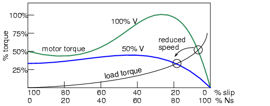
Slip angle, unfortunately, is not stationary as a PMDC. One can increase slip frequency, but this is somewhat equivalent to more powerful magnets on a BLDC only. There's not a lot to know here: The rotor is a secondary of a transformer, the stator is the primary. The larger the primary magnetic field (input voltage) and frequency difference between the rotor and stator (slip frequency or n) the larger the secondary current and hence the larger the flux, resulting in an increase in torque. With limits, because the rotor can saturate, basically creating a short circuit.
Regarding boost, in order for an inductor to "boost" the magnetic field must be collapsing (ie, input power removed). This is the opposite requirement to generate torque. Sure the motor can be used as a large inductor for boost purposes, but doing so while operating will only create drag and on case of an induction motor it will not generate useful magnetizing current for the rotor (The sum of the 3 phase currents going to the motor is 0A, disturbing this would generate an inbalance).
Paul, please have a look at this file:
https://www.rockwellautomation.com/r...ion_motors.pdf |
|
|
|
|
The Following 2 Users Say Thank You to cts_casemod For This Useful Post:
|
|
|
01-08-2015, 12:22 PM
|
#1536 (permalink)
|
|
Master EcoModder
Join Date: Oct 2012
Location: USA
Posts: 1,408
Thanks: 102
Thanked 252 Times in 204 Posts
|
from the link, "The stopped induction motor acts like a transformer shorted on the secondary side."
ok, that sounds like something of a deal killer for motor as battery charger or random inductor, but also kinda explains why a higher resistance rotor makes more torque off the line.
|
|
|
|
|
01-08-2015, 12:33 PM
|
#1537 (permalink)
|
|
EcoModding Apprentice
Join Date: Nov 2012
Location: East Midlands
Posts: 180
Thanks: 13
Thanked 81 Times in 52 Posts
|
Quote:
Originally Posted by P-hack
from the link, "The stopped induction motor acts like a transformer shorted on the secondary side."
ok, that sounds like something of a deal killer for motor as battery charger or random inductor
|
As a random inductor/battery charger, no current is being generated on the rotor. Its just sitting there, probably adding some more magnetic material. the real killer are the higher copper resistance (mine is 2.1Ohm P-P) and the magnetic losses.
Quote:
Originally Posted by P-hack
... but also kinda explains why a higher resistance rotor makes more torque off the line.
|
Almost. It doesn't necessarily produce more torque, but it does the same amount of torque with less current from the primary, requiring a larger slip. They are particularly suited for motors that have to be started across the line with heavy loads as the current draw and power factor are quite good, but have poor speed regulation. |
|
|
|
|
01-08-2015, 01:46 PM
|
#1538 (permalink)
|
|
PaulH
Join Date: Feb 2008
Location: Maricopa, AZ (sort of. Actually outside of town)
Posts: 3,832
Thanks: 1,362
Thanked 1,202 Times in 765 Posts
|
I've been doing more figgerin with an inductor core. This time I think I understand the process. Adam Brunette had recommended the E827 core family from micrometals.com. Specifically E827-2. I would use 6" wide copper sheet and nomex for doing a single roll that's around 25 feet long, and close the 2 E's around the roll.
I worked through all the formulas and finally think I understand the process. The core loss is very reasonable with that core. At 400amp, 144v input, at 10KHz and 100uH inductor, it would be about 35 watts of waste heat in the core. That's certainly manageable. And it's a beefcare core too. around 6Kg per half.
https://www.dropbox.com/s/wasp3nr1mt...Sheet.pdf?dl=0 |
|
|
|
|
01-08-2015, 03:17 PM
|
#1539 (permalink)
|
|
Master EcoModder
Join Date: Oct 2012
Location: USA
Posts: 1,408
Thanks: 102
Thanked 252 Times in 204 Posts
|
so like 25 turns?
FYI, a foil wrapped gapped e-core has some optimization possibilities:
http://www.wcmagnetics.com/images/pd...l-inductor.pdf |
|
|
|
|
The Following User Says Thank You to P-hack For This Useful Post:
|
|
|
01-08-2015, 03:42 PM
|
#1540 (permalink)
|
|
PaulH
Join Date: Feb 2008
Location: Maricopa, AZ (sort of. Actually outside of town)
Posts: 3,832
Thanks: 1,362
Thanked 1,202 Times in 765 Posts
|
That was fascinating! Keeping the copper away from the air gap to reduce AC losses. I sure am learning a lot about this stuff. It is weird.
|
|
|
|
|


