 01-14-2016, 05:01 PM
|
#2531 (permalink)
|
|
Master EcoModder
Join Date: Oct 2012
Location: USA
Posts: 1,408
Thanks: 102
Thanked 252 Times in 204 Posts
|
it could use better software, hoping the seek folks figure out how to add sound and maybe a gradient to the recording.
it can display min and max and display them on the screen location. Or it can do a threshold, or pinpoint temp, I don't think they get recorded though, so you will want to read out min/max on something that records sound occasionally.
fyi, no cats in this house  that is our younger dog sleeping on a footstool.
lots of stuff,
google seek thermal xr
http://www.amazon.com/gp/customer-reviews/R361YH99F550TI/ref=cm_cr_pr_viewpnt?ie=UTF8&ASIN=B00NYWAHHM#R361Y H99F550TI
check the compatibility lists and etc.
|
|
|

|
 Today Today
|
|
|
|
 Other popular topics in this forum...
|
|
|
|
|
01-14-2016, 06:31 PM
|
#2532 (permalink)
|
|
Master EcoModder
Join Date: Sep 2010
Location: Saskatoon, canada
Posts: 1,488
Thanks: 746
Thanked 565 Times in 447 Posts
|
Quote:
Originally Posted by e*clipse

Hmm - yea - I was just reading the #'s on the DI-149 I have. I try to keep all the voltages down in the +/-5V range, just 'cause the microcontroller works that way. Most things like temp sensors, pressure sensors, etc etc work in the 5V range. The software makes calibration really easy, so reading the output of the current sensor and graphing it as +/- 300A vs 0>5V is easy to set up.
For something like battery voltage, a simple voltage divider will work to bring it down to an acceptable level for testing.
- E*clipse
|
Scaling the voltage is pretty easy - the pack is 125V so 0 - 5V would require a divide by 25. Maybe a 26K in series with a 1K2. With a 10 bit A/D you have 1024 counts. So 0V = 0 counts and 1024 counts = about 125V. That resolution is pretty good at about 0.12V per count.
The current is a bit more of a challenge. The shunt resistor is 50 amps = 50 mv for a resistance of about 1 milli-ohm. The ad lists 10 bit A/D, so 1024 counts from 0 - 5V, or 4.88 mv per 'count'. With a 50 amp, 50 mv shunt there is 10 counts between 0 and 50 amps. The measurements are normally +/- 1 count for a lab, more like +/- 5 counts in my garage. I don't really expect more than 500 amps, so I'm using 100 counts out of the 1024 counts in the A/D for a short time. I would expect to be below 250 amps for the rest of the testing. IF I can get a DC controller working, I'd be under 125 amps for most of the testing.
I could add an amplifier, but that requires an op-amp and several more connections, plus many additional sources of noise for the signal being measured. In my limited experience with amplifiers, you don't get much additional accuracy on your measurements unless you make a PCB. Breadboarding is quick, but not perfect.
This may not be a good fit ... at least for the current measurement |
|
|
|
|
01-14-2016, 09:13 PM
|
#2533 (permalink)
|
|
Master EcoModder
Join Date: Sep 2010
Location: Saskatoon, canada
Posts: 1,488
Thanks: 746
Thanked 565 Times in 447 Posts
|
Quote:
Originally Posted by freebeard
Not having seen the layout in your garage, this is speculation, but...
Place a large mirror at 45° to the gauges. Place a small mirror to occlude half (or 1/4th) the field of view in front of the camera. Place the camera so that gauges are visible.
Everything will sync at the speed of light.
|
The meters (they are paired. voltage and current for each location) are close to the battery pack and to the DC motor. The meters are about 4 feet apart, and about 3 feet different in elevation (floor versus on top of battery pack)
Mirrors would need to be paired to keep from having the image reversed ... a bit of a challenge to support the mirrors and get the angles right, with enough rigidity to keep the mirrors from vibrating .. but it is an option. It would limit the video to a specific angle, but taking video of the meters will take a dedicated camera anyway.
I didn't think much of the idea at first .. but it's kinda growing on me .. |
|
|
|
|
The Following User Says Thank You to thingstodo For This Useful Post:
|
|
|
01-15-2016, 06:21 PM
|
#2534 (permalink)
|
|
Permanent Apprentice
Join Date: Jul 2010
Location: norcal oosae
Posts: 523
Thanks: 351
Thanked 318 Times in 215 Posts
|
Quote:
Originally Posted by thingstodo
Scaling the voltage is pretty easy - the pack is 125V so 0 - 5V would require a divide by 25. Maybe a 26K in series with a 1K2. With a 10 bit A/D you have 1024 counts. So 0V = 0 counts and 1024 counts = about 125V. That resolution is pretty good at about 0.12V per count.
The current is a bit more of a challenge. The shunt resistor is 50 amps = 50 mv for a resistance of about 1 milli-ohm. The ad lists 10 bit A/D, so 1024 counts from 0 - 5V, or 4.88 mv per 'count'. With a 50 amp, 50 mv shunt there is 10 counts between 0 and 50 amps. The measurements are normally +/- 1 count for a lab, more like +/- 5 counts in my garage. I don't really expect more than 500 amps, so I'm using 100 counts out of the 1024 counts in the A/D for a short time. I would expect to be below 250 amps for the rest of the testing. IF I can get a DC controller working, I'd be under 125 amps for most of the testing.
I could add an amplifier, but that requires an op-amp and several more connections, plus many additional sources of noise for the signal being measured. In my limited experience with amplifiers, you don't get much additional accuracy on your measurements unless you make a PCB. Breadboarding is quick, but not perfect.
This may not be a good fit ... at least for the current measurement
|
I just reviewed my test, using the slightly less capable DI-145.
I'll try to post some pics of the test rig and output.
The test was controlling a double DC motor powered differential-steer tracked vehicle. I wanted to find out how controllable it is and how much power it used. Each motor had a 12V lead acid battery that was connected directly on the positive side to a contactor and then the motor. The motors' negatives were connected together then through one lead back to the two batteries.
Control was on-off with the contactors. In the end it was pretty controllable with that simple set-up and I did a bunch of running up and down the driveway tests, along with hill climbs, etc.
To measure performance, I connected the 12V from the battery after each contactor directly to the DI-145. With this setup, I could later see which motor was on, voltage drop, etc.
For measuring current, I used a LEM current sensor. I ran the return line from the motors through the LEM. I have a bunch of little dc-dc converters that I use for random stuff. I just connected one of those so that 12V from the battery to supply 5V for the LEM. I just wired the LEM's output directly to the DI-145 and scaled the output according to the LEM's specs. I connected the DI-145 directly to my laptop on the seat next to me and went for a ride.
With this admittedly very hokey rig, I got some very useful and repeatable data. The DI-145 put out 4 data tracks that were sinc'd along with a time signature. I could see how extra current draw pulled the individual batteries down, how using only one motor (to turn) affected the overall power output, etc etc. The current measurement was so sensitive that I could tell by looking at the output where exactly I was in my driveway at a particular time. It would track the 425A startup spike along with the normal 50A +/- 10A (depending on conditions) running current.
I'll post some test rig pics tonight.
- E*clipse |
|
|
|
|
The Following User Says Thank You to e*clipse For This Useful Post:
|
|
|
01-16-2016, 12:21 AM
|
#2535 (permalink)
|
|
Permanent Apprentice
Join Date: Jul 2010
Location: norcal oosae
Posts: 523
Thanks: 351
Thanked 318 Times in 215 Posts
|
Ok, as promised here are some pics showing the test. Paul - I would like to apologize in advance because these pics have nothing to do with AC motor controllers. I'm absolutely not trying to hijack this thread, just show some testing with a DI-145.
First, here is the test subject:
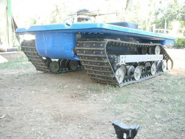
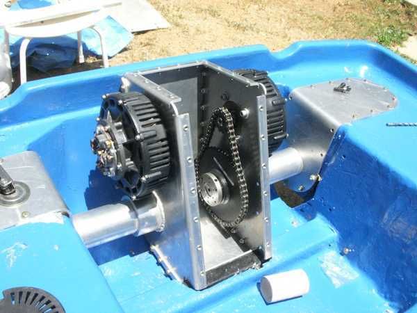
Second, here is the completely rebuilt drive system. Instead of a two cylinder pukey gas engine with a hydraulic drive system, there is the simple elegance of two electric motors.
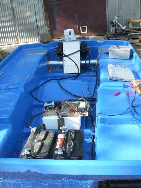
Here is the ready to go test rig, wired as described in the previous post. Everything was logged on the laptop sitting on the right side. The grey electric box has all the "controls" - basically on/off switches to drive the contactors. The wooden board near the center has all the test and control stuff. On the left side are two Gigavac contactors. Near the center is the little DCtoDC converter, and on the right side is the DI-145. If you look close, you can see the LEM current sensor to the right of the right side battery.
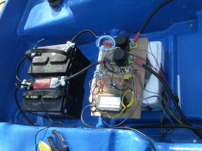
Here is a close up of the "control" board. LOL!  Boy I never thought I'd post this....
The cable from the LEM is shielded, going to a plug that allows me to disconnect it from the test rig. From the Plug it's wired to the DI-145.
This is an example of the output. Top row is the current, as measured by the LEM, and the bottom two rows are the individual battery voltages. In this example, you can see the inrush current and how it pulls down the battery voltage. There are also two square peaks in the bottom voltage - this corresponds to a place where I turned off the right side motor to turn. The opposite motor actually has to pull harder to make up the difference - you can see that in the current trace and the opposite motor's voltage.
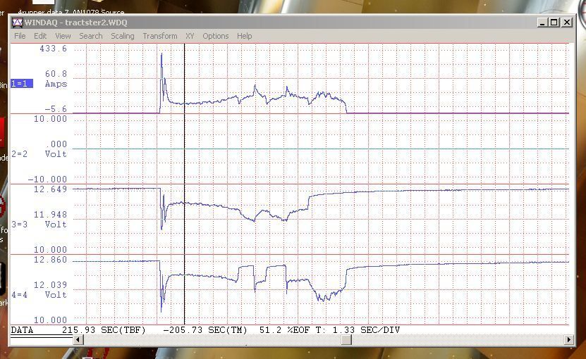
Anyway, as you can see it's possible to do much more sophisticated testing than this example. But I was still able to get some important information about the performance of this system.
- E*clipse |
|
|
|
|
The Following 5 Users Say Thank You to e*clipse For This Useful Post:
|
|
|
01-16-2016, 10:35 AM
|
#2536 (permalink)
|
|
AC-DC enthusiast
Join Date: Nov 2009
Location: Long Island, NY
Posts: 282
Thanks: 123
Thanked 54 Times in 37 Posts
|
what type of speed are we talking about with this bathtub? 5, 10, 15.....Will,it float?
__________________
. .. .. . .... . .... ... ...
Prius Absolutum Dominium . ..........KOPPER
PHEV conversion since Dec 2006.. . .... .Future EV
. . . . . . . .CALCars # 27. . . . . . . . . . ..on the works now !!
. . . . . . . . . . . . . . . . .. . ........
|
|
|
|
|
01-16-2016, 01:02 PM
|
#2537 (permalink)
|
|
Master EcoModder
Join Date: Aug 2012
Location: northwest of normal
Posts: 29,162
Thanks: 8,278
Thanked 9,041 Times in 7,472 Posts
|
It's nice to see a running vehicle.
|
|
|
|
|
The Following User Says Thank You to freebeard For This Useful Post:
|
|
|
01-16-2016, 04:07 PM
|
#2538 (permalink)
|
|
Permanent Apprentice
Join Date: Jul 2010
Location: norcal oosae
Posts: 523
Thanks: 351
Thanked 318 Times in 215 Posts
|
Quote:
Originally Posted by freebeard
It's nice to see a running vehicle.
|
Just to answer a couple questions - again I don't want to get off track here.
The original vehicle was the Cushman Trakster. The original design did float, but this one's "bathtub" was so abused and cut up, it would be a major amount of work to fix. I've already done a huge amound of fiberglass repair work just to fix the structural integrity.
The tests were run at a "fast walk" - about 3mph or so, using roughly 12V per motor. Calculations based on the motor's voltage capability are in the 18mph > 20mph range. So far all my calcs are very close.
Right now I'm designing the BMS for a 1/2 Nissan Leaf Lithium Ion battery pack for it. I'm also making a double H-bridge 4 quadrant controller for it. The original vehicle was very easy to control - I'm going to make this one even easier.
- E*clipse |
|
|
|
|
The Following User Says Thank You to e*clipse For This Useful Post:
|
|
|
01-16-2016, 11:29 PM
|
#2539 (permalink)
|
|
Master EcoModder
Join Date: Sep 2010
Location: Saskatoon, canada
Posts: 1,488
Thanks: 746
Thanked 565 Times in 447 Posts
|
Update for Jan 16
I gave up on editing the video for the AC Controller testing I did for Dec 21. As you had all suggested. The log files are attached with a spreadsheet that I used to enter the DC Volts and amps that I read on the audio as well as the approximate rpm that I read them at. I then matched up the DC volts and Amps on the high voltage pack from the separate video. The video from the DC motor amps and volts did not work out. The audio from my headset did not work out. So this is what I was able to salvage.
|
|
|
|
|
01-16-2016, 11:31 PM
|
#2540 (permalink)
|
|
Master EcoModder
Join Date: Sep 2010
Location: Saskatoon, canada
Posts: 1,488
Thanks: 746
Thanked 565 Times in 447 Posts
|
Jan 13 update continued
My conclusions from this test:
- the AC controller works fine up to Id = 330 amps
- the mechanical rpm measurement works fine
- recording video makes it a lot easier to synchronize the readings
A few things I learned:
- I should not panic when I smell electrical varnish. George Hamstra had warned me that if the warp 9 motor had not been in a car, had not been subject to load on it for maybe half an hour at a time, the varnish would smell a bit as it finished it's curing
- Regen brakes only regen to a certain speed, based on the torque you command. I was pumping 20 amps at 122V FROM the High voltage pack near the end of the test .. into the AC controller ... to have the AC motor slow down my DC motor. The DC motor was taking 270 amps at a voltage between 20 and 23V at the time. 2440W from the High voltage pack, maybe 5500W from the low voltage pack, ALL going into heating up the controller and the motors.
- the temp was up to 75C at the end of the test, but that was much higher than I got from my handheld thermometer. I got about 17.7C on the large heat sink, 27.0C on the spreader and 49.7C as the hottest that any part of the IGBT surface is. So the toothpaste is OK as thermal paste .. but the internal heat really gets much higher than the surface of the heat spreader shows.
Some things that may not be working on the AC controller:
- the Vd measurement may not be working. It did not seem to change during the test
- the battery amps don't match too well for the high voltage pack. Not sure why. 20 measured versus 32 logged, 4 measured versus 9.5 logged, 30.5 measured versus 43 logged.
|
|
|
|
|
The Following 2 Users Say Thank You to thingstodo For This Useful Post:
|
|
|


