Go Back   EcoModder Forum > EcoModding > Fossil Fuel Free
Register Now
 Register Now
 

Reply  Post New Thread
 
Submit Tools LinkBack Thread Tools
Old 01-16-2016, 10:33 PM   #2541 (permalink)
Master EcoModder
 
Join Date: Sep 2010
Location: Saskatoon, canada
Posts: 1,488

Ford Prefect - '18 Ford F150 XLT XTR

Tess - '22 Tesla Y LR
Thanks: 749
Thanked 565 Times in 447 Posts
Plans for the next test

So I think that the next test needs to be a bit slower at the beginning:
- get the audio verified
- get the videos running
- log the temperatures on audio, leave the thermometer by the controller, turned on
- start the AC logging
- start up the AC controller
- use the throttle to start up the AC motor (so I verify that the controller is taking current)
- *EDIT* check the AC output voltage with a meter as a check for the logging
- start up the DC motor, get up over 3600 rpm
- adjust the throttle to take less and less current until we it is in regen and showing the battery pack higher than it was at the start.
- log the heat spreader temp

That's the slow part, now for the fast part
- increase the load very quickly with the throttle until the controller reaches 300 AC amps
- Increase quickly .. 300, 350, 400, ... monitor the controller temperature
- shut it down with the ESTOP when it reaches ... 100C? The max operating temp is 125C

Paul - if you can confirm the max temp for the IGBTs on your spec sheet please? I found a Powerex 600V 600A spec sheet, but it may not be identical. 125C operating, 150C max

That should be about it!


Last edited by thingstodo; 01-17-2016 at 03:08 PM.. Reason: Add a step
  Reply With Quote
The Following User Says Thank You to thingstodo For This Useful Post:
MPaulHolmes (01-17-2016)
Alt Today
Popular topics

Other popular topics in this forum...

   
Old 01-17-2016, 02:31 PM   #2542 (permalink)
Somewhat crazed
 
Piotrsko's Avatar
 
Join Date: Sep 2013
Location: 1826 miles WSW of Normal
Posts: 4,043
Thanks: 462
Thanked 1,104 Times in 974 Posts
I have found that my sample on the digital current meter varies all over the place dependent on system voltage, power loads, and what part of the time frame it sampled at. On the Sol1 and dc motor the current jumps all over the place from 0 to Imax. You can see it on a 500 ua meter needle.
__________________
casual notes from the underground:There are some "experts" out there that in reality don't have a clue as to what they are doing.
  Reply With Quote
Old 01-17-2016, 03:09 PM   #2543 (permalink)
Master EcoModder
 
Join Date: Sep 2010
Location: Saskatoon, canada
Posts: 1,488

Ford Prefect - '18 Ford F150 XLT XTR

Tess - '22 Tesla Y LR
Thanks: 749
Thanked 565 Times in 447 Posts
Quote:
Originally Posted by Piotrsko View Post
I have found that my sample on the digital current meter varies all over the place dependent on system voltage, power loads, and what part of the time frame it sampled at. On the Sol1 and dc motor the current jumps all over the place from 0 to Imax. You can see it on a 500 ua meter needle.
So you see the current bouncing on the digital meter as well as the analog needle? How does one get a reasonable number?
  Reply With Quote
Old 01-17-2016, 06:46 PM   #2544 (permalink)
Somewhat crazed
 
Piotrsko's Avatar
 
Join Date: Sep 2013
Location: 1826 miles WSW of Normal
Posts: 4,043
Thanks: 462
Thanked 1,104 Times in 974 Posts
Averaging or many fast samples. possibly capacitive smoothing on batteries.

If the pedal is floored with heavy pressure, current should slowly trend down as I hit bemf. The digital shows anywhere from 400 to 450 amps, too much current on the shunt for the analog which is pegged.
__________________
casual notes from the underground:There are some "experts" out there that in reality don't have a clue as to what they are doing.

Last edited by Piotrsko; 01-17-2016 at 06:54 PM..
  Reply With Quote
The Following User Says Thank You to Piotrsko For This Useful Post:
e*clipse (01-19-2016)
Old 01-17-2016, 11:36 PM   #2545 (permalink)
PaulH
 
MPaulHolmes's Avatar
 
Join Date: Feb 2008
Location: Maricopa, AZ (sort of. Actually outside of town)
Posts: 3,832

Michael's Electric Beetle - '71 Volkswagen Superbeetle 500000
Thanks: 1,368
Thanked 1,202 Times in 765 Posts
Wow I just thought I'd check the thread. This was very eventful!!! That bathtub tank is the coolest thing I have ever seen!

I just checked the datasheet:
http://www.pwrx.com/pwrx/docs/cm600dy_12nf.pdf

So, a JUNCTION (inside the IGBT) temperature of 150degC max. The IGBTs are 0.11degC/Watt from junction to case. So, 100watt burning up inside one of the IGBTs (high or low side) means the junction is 11 degrees hotter than the case. So, we could figure out the junction temperature if we know the base plate temp and the amount of heat being generated inside. But there are 2 IGBTs per package, so I guess 200w would mean 11degC hotter, since each IGBT could be burning 100w.
__________________
kits and boards

Last edited by MPaulHolmes; 01-18-2016 at 10:18 AM..
  Reply With Quote
The Following User Says Thank You to MPaulHolmes For This Useful Post:
e*clipse (01-19-2016)
Old 01-18-2016, 03:20 PM   #2546 (permalink)
Master EcoModder
 
Join Date: Sep 2010
Location: Saskatoon, canada
Posts: 1,488

Ford Prefect - '18 Ford F150 XLT XTR

Tess - '22 Tesla Y LR
Thanks: 749
Thanked 565 Times in 447 Posts
Quote:
Originally Posted by MPaulHolmes View Post
I just checked the datasheet:
http://www.pwrx.com/pwrx/docs/cm600dy_12nf.pdf

So, a JUNCTION (inside the IGBT) temperature of 150degC max. The IGBTs are 0.11degC/Watt from junction to case. So, 100watt burning up inside one of the IGBTs (high or low side) means the junction is 11 degrees hotter than the case. So, we could figure out the junction temperature if we know the base plate temp and the amount of heat being generated inside.
I think that, after I load the new firmware, it would be good if I checked that:
1 save works
2 logging works
3 regen stops turning the motor when the motor reaches 0 rpm

When those are successful, I can do the motoring/regen test that I had described, to verify when the motor is taking power out of the high voltage pack, and when it switches to generating power into the pack.

After that, I'll limit the test to 200 AC amps to begin with, and run it for a few minutes to check on the measured temperature. Then I'll shut off the DC motor and let the AC controller keep logging so that I can see what the temperature ends up rising to (if it keeps rising at all)

---------------------------------------------------------------------------------------
So this is some rambling, talking things through and making some simplifications so I can do back-of-the-envelope calculations. Please point out any errors!

/Begin Ramble

Worst-case Voltage drop from Collector to Emitter Vce = 2.2V
Worst-case on switching time . I think .. 300 rise time
Worst-case off switching time ... 300 ns fall

I'll simplify the voltage to 100V instead of 125V
and I'll simplify the switching speed to 10 Khz instead of .. was it 8?

300 ns * 100V * I = rising loss
300 ns * 100V * I = falling loss

Let's say 100 amps per IGBT for argument's sake (and simpler numbers)
rising loss = 300 ns * 100V * 100 amps = 3 mw (is that the right units?)
falling loss = 300 ns * 100V * 100 amps = 3 mw

So 6 mw per cycle * 10,000 times per second = 60W

10 Khz waveform takes 100 ms per cycle. Max duty cycle .. 90% ?
.. so 100 amps * 2.2V drop * 90 ms * 10000 cycles/second = 198W. Worst case.

Total power dissipation at 90% duty cycle = 60 + 198 = 260W per 100A of current

Paul, I think you said that your hardware over-current is set to 450 amps per IGBT. I'm not sure if that is RMS or peak. * root 3 for three phase (to count the other two phases .. just a formula) = 780 amps if it was RMS, or 550 amps if it was peak.

I'll be lucky if my test rig will stand up to that current. So using 450 amps per IGBT, that is 4.5X what I have calculated above for 100 amps, 4.5 * 260W = 1170W. Per IGBT. That's a 3500W heater!

1170W * 0.11C/W = 128C .. is that right? The junction temp can be 128C higher than the case temperatures!??!?!?

150C - 128C = 22C with no safety factor .. that's just not practical! Keeping the heat spreader plate at 22C would require the heat spreader to be sitting in ice water ...

Paul, where is the temperature sensor .. exactly? Any idea what is realistic to use as a shutdown temp?

My last test ended at 75C measured by the controller .. but I shut down the controller so I was not able to continue logging the temperatures to see if it climbed after the test ended. I think I will have to keep the AC controller online and logging, just shut down the DC motor? Or maybe shut down both and turn the AC controller back on and continue logging? Not sure.

I think I'm using worst case on everything .. but the simplifications are skewing everything so there is no safety factor. Maybe that's why the datasheet posts the curves instead of using the simplifications that I'm using!

As for maximums - the IGBTs are rated for 1130W each max dissipation. So it looks like maybe 450 amps per IGBT at 100V is too much? Perhaps your 450A is a realistic maximum for a short period of time (like maybe 15 seconds).

/End Ramble
  Reply With Quote
Old 01-19-2016, 06:22 PM   #2547 (permalink)
Permanent Apprentice
 
Join Date: Jul 2010
Location: norcal oosae
Posts: 523
Thanks: 351
Thanked 314 Times in 215 Posts
Quote:
Originally Posted by Piotrsko View Post
Averaging or many fast samples. possibly capacitive smoothing on batteries.

If the pedal is floored with heavy pressure, current should slowly trend down as I hit bemf. The digital shows anywhere from 400 to 450 amps, too much current on the shunt for the analog which is pegged.
That's exactly what happened in my tests. If you look close at the graph in post# 2534, that initial spike is over 400A. The current then ramps down in about 1 second. My control was ON/OFF with a contactor, so it was a very heavy foot - LOL! 
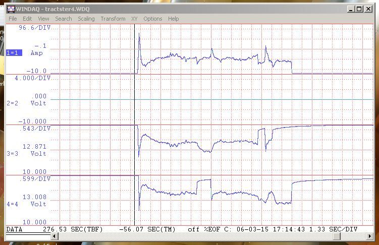
For some reason in this graph there was a quick drop in current, which then resumed, following the ramp down trend. I may have let go of the control or something; I'm not sure. The other graphs I have don't have that drop-out anomoly. OTOH, they all spike up and ramp down in about 1 second.

A person can choose faster sample times, I chose this rather course sample time because I was doing longer tests and I was looking at general trends.

- E*clipse
  Reply With Quote
Old 01-20-2016, 02:38 PM   #2548 (permalink)
Somewhat crazed
 
Piotrsko's Avatar
 
Join Date: Sep 2013
Location: 1826 miles WSW of Normal
Posts: 4,043
Thanks: 462
Thanked 1,104 Times in 974 Posts
Actually it looks like overshoot oscillation on the control circuit, at least to me which is funny for a switch.
__________________
casual notes from the underground:There are some "experts" out there that in reality don't have a clue as to what they are doing.

Last edited by Piotrsko; 01-20-2016 at 02:45 PM..
  Reply With Quote
Old 01-20-2016, 03:31 PM   #2549 (permalink)
Permanent Apprentice
 
Join Date: Jul 2010
Location: norcal oosae
Posts: 523
Thanks: 351
Thanked 314 Times in 215 Posts
Quote:
Originally Posted by Piotrsko View Post
Actually it looks like overshoot oscillation on the control circuit, at least to me which is funny for a switch.


There is no control circuit. It is simply a contactor. Look at the picture above it. See the Gigavac contactors? That's all there is. That grey control box only holds a primary on/off switch and two momentary pushbuttons, each directly connected to a contactor. There is no controller, no "reference" current level to oscillate around. The current simply peaks then decays. That second peak is simply me letting go of the contactors' "on" buttons, probably because the thing jumps to full speed and it's difficult to hold onto the the control box, two buttons and not fall out. The two peaks don't exist in any of my other tests because I learned to drive.

  Reply With Quote
The Following User Says Thank You to e*clipse For This Useful Post:
MPaulHolmes (01-21-2016)
Old 01-22-2016, 11:39 PM   #2550 (permalink)
Master EcoModder
 
Join Date: Sep 2010
Location: Saskatoon, canada
Posts: 1,488

Ford Prefect - '18 Ford F150 XLT XTR

Tess - '22 Tesla Y LR
Thanks: 749
Thanked 565 Times in 447 Posts
Update from Jan 22

A rarity - I got 20 minutes to try Paul's new firmware, at least in a limited way, and I'm getting the results posted ON THE SAME DAY!

Without video, since I did not stop to set up the video ... but still POSTED!

The Jan 18 firmware loaded fine, and it spun up the motor without modification. Jan22.txt shows that part .. but there is not much to show since it was not logging.

After that success, I loaded the XAC_config.txt file, which is my AC_Config file with all of the settings removed, just setting the flags for logging data.

Jan22 1.txt is the result of starting up the AC motor, accelerating to 3600 rpm (maybe 3700), then doing a hard regen until it stops.

The AC motor no longer spins backward in 'regen braking'. It comes nicely to a stop and you can hear the controller output turn off (the whine stops).

Files attached in case there is something interesting.

Attached Files
File Type: txt jan22.txt (3.5 KB, 12 views)
File Type: txt xac_config.txt (394 Bytes, 21 views)
File Type: txt jan22 1.txt (6.0 KB, 10 views)
  Reply With Quote
The Following 2 Users Say Thank You to thingstodo For This Useful Post:
Astro (01-24-2016), MPaulHolmes (01-23-2016)
Reply  Post New Thread


Thread Tools


Similar Threads
Thread Thread Starter Forum Replies Last Post
Paul & Sabrina's cheap DIY 144v motor controller MPaulHolmes Open ReVolt: open source DC motor controller 7381 08-02-2023 10:55 PM
Paul & Sabrina's Cheap EV Conversion MPaulHolmes Fossil Fuel Free 542 11-12-2016 09:09 PM
Contest! Name Paul & Sabrina's controller MetroMPG Forum News & Feedback 120 10-22-2011 01:59 PM


Powered by vBulletin® Version 3.8.11
Copyright ©2000 - 2024, vBulletin Solutions Inc.
Content Relevant URLs by vBSEO 3.5.2
All content copyright EcoModder.com