 05-14-2012, 04:39 AM
|
#721 (permalink)
|
|
EcoModding Lurker
Join Date: Jul 2011
Location: France
Posts: 90
Thanks: 3
Thanked 65 Times in 30 Posts
|
Quote:
Originally Posted by thingstodo

I think that what Paul said is that he's measuring 2 currents at the same time and that this is enough information.
|
Yes absolutely, I do the same on my FOC PMAC controller
Quote:
Originally Posted by thingstodo
- the hall effect current sensors are on the three output phases, after the IGBTs
- phase to phase issues can be detected in the motor by comparing phase currents
- phase to ground issues can be detected in the motor by having the currents not add to 0
|
In my case, for short circuit detection I don't use software, because the current measurement is done on the middle of the voltage pulse, and it can be really too long to protect the mosfet/igbt. Thus my 2 current sensor outputs are connected to my 2 ADC input, but also each current sensor output enters in two op amp comparators : if the sensor current signal go above a high threshold (positive current) or go below a low threshold (negative current), the comparator output (all outputs are /ORed) trigger the /fault entry of the microcontroller, which instantaneously shut down the PWM signals.
Thus in my case short circuit detection is done in hardware. With 2 current sensors 2 phases are completely protected, the third is not hardware protected against phase to V+ or V- short circuit (only phase to phase short circuit).
But it's easy to add the third sensor to do that, can be useful for big and expensive controller. But it's not mandatory to connect the third current sensor output to an adc input (can be only connected to the hardware comparators), except if it's also needed to do software verification (3 currents sums to zero), to detect motor or current sensor problem.
|
|
|

|
 Today Today
|
|
|
|
 Other popular topics in this forum...
|
|
|
|
|
05-14-2012, 08:44 AM
|
#722 (permalink)
|
|
PaulH
Join Date: Feb 2008
Location: Maricopa, AZ (sort of. Actually outside of town)
Posts: 3,832
Thanks: 1,362
Thanked 1,202 Times in 765 Posts
|
Quote:
|
if the sensor current signal go above a high threshold (positive current) or go below a low threshold (negative current), the comparator output (all outputs are /ORed) trigger the /fault entry of the microcontroller, which instantaneously shut down the PWM signals.
|
That's exactly what I do too. I also add some NAND flip-flops and a p-channel mosfet so that Vcc of all high side optocouplers goes to zero. |
|
|
|
|
05-31-2012, 11:38 AM
|
#723 (permalink)
|
|
PaulH
Join Date: Feb 2008
Location: Maricopa, AZ (sort of. Actually outside of town)
Posts: 3,832
Thanks: 1,362
Thanked 1,202 Times in 765 Posts
|
Should be done assembling the prototype by Friday!
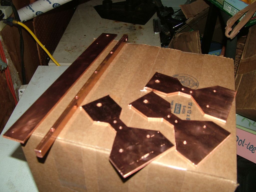
One of the 3 phase bars:
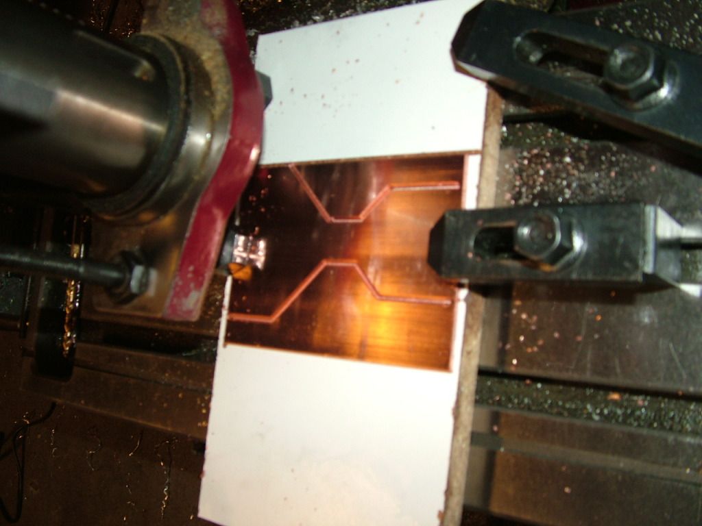
From left to right, B+ bar, B- bar, phase 1, 2, and 3 bars. No risk of mixing those up! haha:
I missed my calling as the crappiest photographer in the world. Sorry so blurry. this is how they will lay against the base plate:
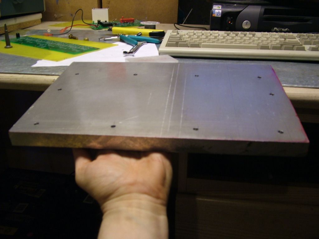
Excuse me, but I believe I ordered the large baseplate. Later I'm going to mill channels in it for water cooling. For now I'll just use it as is for testing.
Everything but the base plate and bus bars:
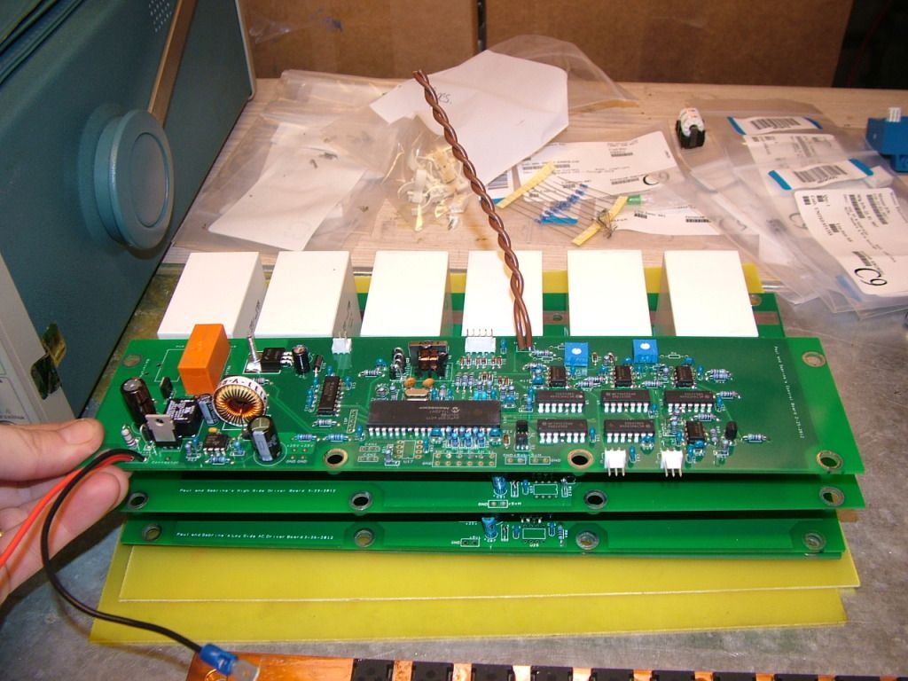
Control board removed:
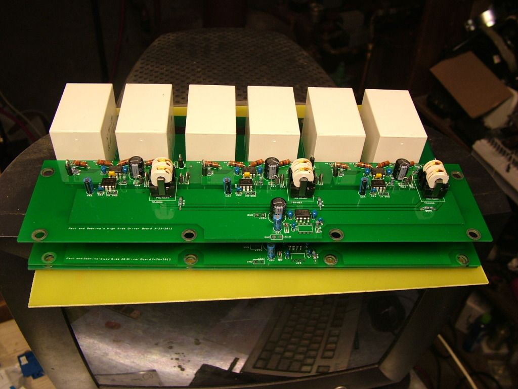
High side driver removed:
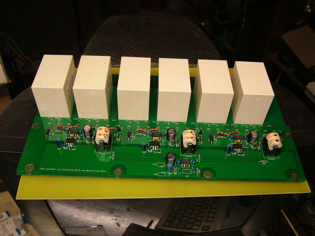
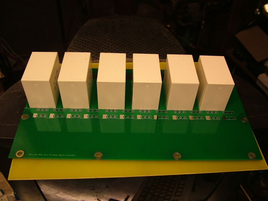
Power board only! Some big friggen film caps. 450v 100uF each.
 |
|
|
|
|
The Following 2 Users Say Thank You to MPaulHolmes For This Useful Post:
|
|
|
05-31-2012, 12:05 PM
|
#724 (permalink)
|
|
EcoModding Lurker
Join Date: Jul 2011
Location: France
Posts: 90
Thanks: 3
Thanked 65 Times in 30 Posts
|
Whouahh !!!
I see the B+ bus bar is directly in contact with the high side mosfets drain, and phase outputs are directly in contact with the low side mosfets drain, thus everything will be probably directly placed and screwed on the base plate ? IE : base pate --> isolation film -> bus bar and phases bar --> mosfets, the screw tightening the 4 together ?
It mean you cannot disassemble everything when the power board is solder on mosfet ?
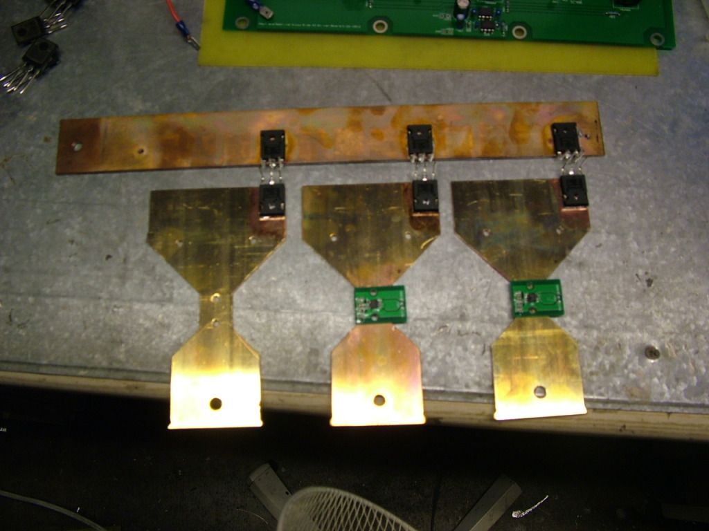
And the 2 small pcb on the phase bar on the right are the current sensors !?? Seems to be great, where do you find that !? Is it hall technology or they measure the small potential difference between the 2 fixation holes ?
|
|
|
|
|
05-31-2012, 12:51 PM
|
#725 (permalink)
|
|
EV test pilot
Join Date: Jan 2008
Location: Oconomowoc, WI, USA
Posts: 4,435
Thanks: 17
Thanked 663 Times in 388 Posts
|
I am in love with those bus bars.
Don't tell my wife!  |
|
|
|
|
05-31-2012, 02:10 PM
|
#726 (permalink)
|
|
PaulH
Join Date: Feb 2008
Location: Maricopa, AZ (sort of. Actually outside of town)
Posts: 3,832
Thanks: 1,362
Thanked 1,202 Times in 765 Posts
|
Quote:
Originally Posted by nlc
IE : base pate --> isolation film -> bus bar and phases bar --> mosfets, the screw tightening the 4 together ?
|
EXACTLY!
Quote:
Originally Posted by nlc
It mean you cannot disassemble everything when the power board is solder on mosfet ?
|
Actually, the bus bars don't get screwed to the base plate, but you put some high temperature silicone on them, and clamp the 2.54mm thick PCB against them, and then solder the mosfets/igbts onto the power board. Then add the drivers and control board. The low side driver is hard to remove because the mosfet legs get soldered right to it.
Quote:
Originally Posted by nlc
And the 2 small pcb on the phase bar on the right are the current sensors !?? Seems to be great, where do you find that !? Is it hall technology or they measure the small potential difference between the 2 fixation holes ?
|
I made the little current sensor boards, and the chip senses the magnetic field, and outputs a voltage. It's a melexis LB that I'm using (low field). This one on that bus bar has a range of around -400 to 400 amps for the full range of 0v to 5v output). I'm only using -300 to 300 or so.
Ben, those bars cheat (cheater bar haha), don't date them. |
|
|
|
|
05-31-2012, 03:06 PM
|
#727 (permalink)
|
|
Master EcoModder
Join Date: Sep 2009
Location: Ireland
Posts: 734
Thanks: 26
Thanked 304 Times in 171 Posts
|
Paul , You Da Man  I want one of those!
__________________
Now, Cole, when you shift the gear and that little needle on the ammeter goes into the red and reads 2000 Amps, that's bad.
www.evbmw.com
|
|
|
|
|
The Following User Says Thank You to jackbauer For This Useful Post:
|
|
|
05-31-2012, 08:57 PM
|
#728 (permalink)
|
|
EcoModding Lurker
Join Date: Apr 2010
Location: Cali
Posts: 35
Thanks: 3
Thanked 4 Times in 3 Posts
|
*drools at the Electrical Engineering porn*
Can't wait to see the results!
|
|
|
|
|
06-04-2012, 04:56 PM
|
#729 (permalink)
|
|
EcoModding Lurker
Join Date: Jun 2012
Location: fghfghfgh
Posts: 5
Thanks: 0
Thanked 0 Times in 0 Posts
|
Paul why do you need -8.2 voltage?
|
|
|
|
|
06-07-2012, 08:51 AM
|
#730 (permalink)
|
|
EcoModding Lurker
Join Date: Jul 2011
Location: France
Posts: 90
Thanks: 3
Thanked 65 Times in 30 Posts
|
Negative voltage is needed on the igbt gate to prevent autoconduction when the igbt is off and the opposite igbt turns on. Also, negative voltage permits to accelerates the turn off time.
|
|
|
|
|


