 11-13-2009, 08:55 PM
|
#2581 (permalink)
|
|
EcoModding Apprentice
Join Date: May 2009
Location: Orrville, Ohio
Posts: 108
Thanks: 9
Thanked 2 Times in 2 Posts
|
Quote:
Originally Posted by jyanof

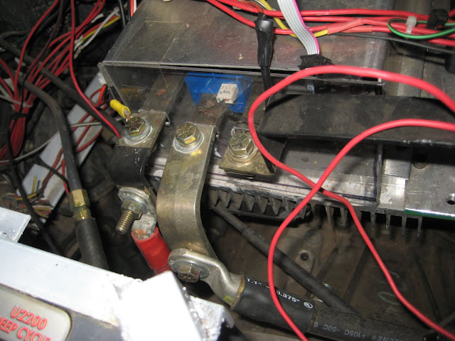
Now that I'm home, I took a picture of the new controller. Yes, all 3 bus bars go out the same direction and I made some bus 'adapter' bars so that the lugs didn't interfere. I did something similar with the Curtis, and no problems so far.
 |
Thanks for the picture. The adapter bars are a good idea. I think when I get to that point, I will try that. Watt.
|
|
|

|
 Today Today
|
|
|
|
 Other popular topics in this forum...
|
|
|
|
 11-13-2009, 10:42 PM
|
#2582 (permalink)
|
|
EcoModding Lurker
Join Date: Sep 2009
Location: Western NY
Posts: 27
Thanks: 5
Thanked 1 Time in 1 Post
|
Paul
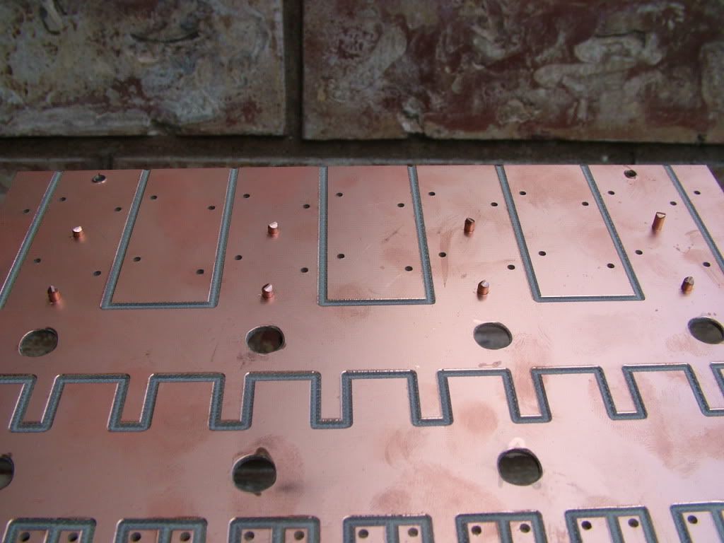
I have more build questions. I got it together with parts left over .... That's never good! I have these little copper bits. Were they supposed to go on the Power Board with the re-enforcing wire? How critical are they to be in there?
John
|
|
|

|
 11-13-2009, 11:23 PM
|
#2583 (permalink)
|
|
PaulH
Join Date: Feb 2008
Location: Maricopa, AZ (sort of. Actually outside of town)
Posts: 3,832
Thanks: 1,362
Thanked 1,202 Times in 765 Posts
|
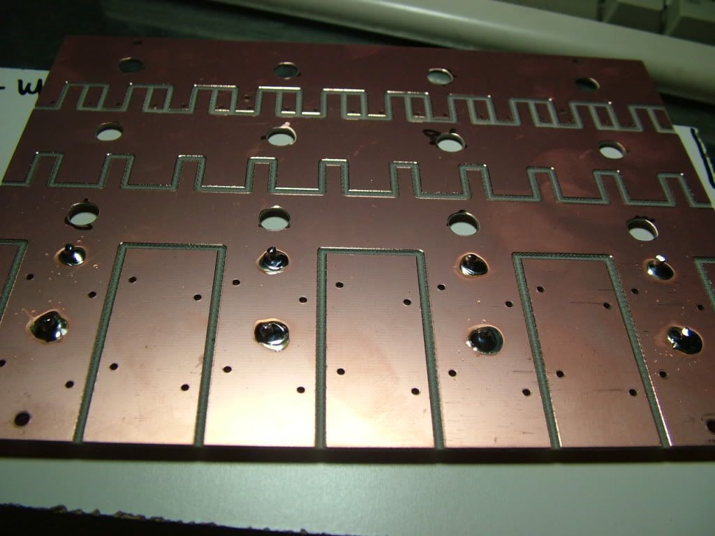
Hi John! It's not a big deal. I'm an idiot. They are vias. I left that part out of the help file. I used to always just solder them in, and then I got lazy and figured that I would just add it to the assembly process, but I left it out of the directions. Check out these pictures:


Here's the work around that you can do:
Add a little supporting copper on the bottom side for the B+ path too. The vias were just there to make the current share between the bottom and top of the pcb, so a little extra on the bottom would do the same thing. In fact, I don't think it's necessary, but it would help keep the pcb cool. I'm sorry about that. |
|
|

|
 11-16-2009, 11:07 AM
|
#2584 (permalink)
|
|
EcoModding Lurker
Join Date: Nov 2009
Location: Long Island, NY
Posts: 83
Thanks: 0
Thanked 9 Times in 9 Posts
|
New member
Dear members: I'm building an electric Sterling. I don't know if I can read the last 100 pgs. I saw a page about the 10k pulldown resistor. I guess you all know that a Mosfet has a very large gate charge, and requires a high current source pulldown to turn off quickly. I called the Warp motor engineer. He said the only two ways people have destroyed their motors was road salt (begs for a belly pan) and overspeed. I'm designing a "body"control board. One feature is 2 microswitches to detect the shifter (VW) in neutral, and prohibit the controller. Who's going to overspeed in one second, in gear? So I think this would save a speed sensor! Also, don't know if this has been covered but a pot module that converts longitudinal motion to rotational, has a transfer function of a parabola, which means very little movement of the pedal (when just cracking the throttle)makes a large rotational change. Is anyone interested in a linear function? Can I download the controller schematic? I designed a controller for a R2D2 robot I built, and I used 20 Hz. The Ford window lift motors did not cog. Curtiss drops to 1.5 Kz to allow small power with less switching loss. But you can use 20 Hz, with very low loss, and less counter EMF energy for the free-wheeling diodes to transfer back into the traction batteries. No "singing" either. Video available of the R2D2 or the chassis I'm arc-welding up. I am a circuit designer. I would be happy to have technical discussions by phone: 631-474-1403. Kindest regards to all, williamson
|
|
|

|
 11-17-2009, 09:35 PM
|
#2585 (permalink)
|
|
Joe
Join Date: Feb 2009
Location: phx
Posts: 260
Thanks: 0
Thanked 48 Times in 38 Posts
|
Quote:
Originally Posted by williamson

Who's going to overspeed in one second, in gear? So I think this would save a speed sensor!
|
I was talking about overspeed with a fellow EVer and he brought up a scenario I hadn't thought of. If some part of the gear train fails (like a weak homemade coupler, or some shaft that is not designed for the torque of a electric motor), it'll likely happen quickly at high amps. Before you know it, that motor could be screaming fast. Only a smart controller would be able to save it (with maybe some drpm/dt limit or something).
Additionally, there's always the case of coasting downhill. There was a guy on the EVDL who shared his pictures of a D&D motor that he blew up. Started at the top of a hill, forgot he was in 1st gear, and around 35 mph the thing blew up... An audible alarm or flashing light could guard from such a $1500 incident (perhaps controlled by the controller too).
Just something to think about. Having said all that, my overspeed hack broke a while ago. I had rigged the shift light on my tach to open a relay to open the main contactor at the specified rpm, but then my tach broke. Now I just make sure to shift at certain speeds... |
|
|

|
 11-18-2009, 09:08 AM
|
#2586 (permalink)
|
|
EcoModding Lurker
Join Date: Apr 2009
Location: Morton, IL
Posts: 38
Thanks: 1
Thanked 1 Time in 1 Post
|
Paul- I heard somewhere that you were interviewed on EVCast. I would like to listen to it without wading through all the episodes. Do you know which number the episode was? Thanks.
__________________
Information should be free. Let's work on that together.
|
|
|

|
 11-18-2009, 10:51 AM
|
#2587 (permalink)
|
|
EcoModding Lurker
Join Date: Nov 2009
Location: Long Island, NY
Posts: 83
Thanks: 0
Thanked 9 Times in 9 Posts
|
Reply to Jyanoff:
Thanks for your reply. Boy, do I have a lot to learn. I never thought of all those reasons. This is the place to learn. I have another idea: starter relays will arc to failure on high voltage DC OR inductive loads. What about the controller commanding 4 external starter relays(a bridge, at the motor cables or battery?), to accomplish "power on-off", (regardless if the driver has a manual circiut-breaker by his right hand), just the usual "power-off-on", and reverse, without an expensive reversing 1000 Amp contactor? The magic would be that the controller could precharge with a MOS-FET. No inductance in a resistor, and inherently fixed current drain. Then after precharge, where the voltage drop is zero, the appropriate relays could close.The controller would wait in the "traction MOS-FETS off" mode, until the relays had kicked in. Also reverse would be "Motor off" switching(as usual). When I talked to the Warp-9 engineer, he said they were going to implement dRPM/dT, to forstall the eve of destruction, exactly as you suggested. Right on! Kindest regards to all, willaimson
|
|
|

|
 11-19-2009, 01:36 AM
|
#2588 (permalink)
|
|
PaulH
Join Date: Feb 2008
Location: Maricopa, AZ (sort of. Actually outside of town)
Posts: 3,832
Thanks: 1,362
Thanked 1,202 Times in 765 Posts
|
|
|
|

|
|
The Following User Says Thank You to MPaulHolmes For This Useful Post:
|
|
 11-19-2009, 09:01 AM
|
#2589 (permalink)
|
|
EcoModding Lurker
Join Date: Apr 2009
Location: Morton, IL
Posts: 38
Thanks: 1
Thanked 1 Time in 1 Post
|
Hey Paul-
I am listening to your interview and I was wondering if you ever thought about a radial design with the MOSFETS to make them all turn on and off at the exact same moment? Or is that not really a concern with less than a 30' controller? Might make it bigger, but just a thought.
__________________
Information should be free. Let's work on that together.
|
|
|

|
 11-19-2009, 10:14 AM
|
#2590 (permalink)
|
|
PaulH
Join Date: Feb 2008
Location: Maricopa, AZ (sort of. Actually outside of town)
Posts: 3,832
Thanks: 1,362
Thanked 1,202 Times in 765 Posts
|
Ya, but there were a few patent issues, since Hazen patented his controller. It is a really good idea though.
|
|
|

|
|