Go Back   EcoModder Forum > EcoModding > Fossil Fuel Free > Open ReVolt: open source DC motor controller
Register Now
 Register Now
 

Reply  Post New Thread
 
Submit Tools LinkBack Thread Tools
Old 03-16-2010, 07:36 AM   #3191 (permalink)
Master EcoModder
 
Join Date: Apr 2009
Location: Charlton MA, USA
Posts: 463

EVVette - '71 Chevy Corvette Coupe
Thanks: 31
Thanked 183 Times in 94 Posts
Quote:
Originally Posted by Flatmann100 View Post
Adam, I looked at the data sheets for the ATMEG168-16PU so, it looks Ok. In the morning I'll have a chance to look at it some more.
The 168 is a direct replacement to the atmega8 chip. It has more memory because the 8 ran out.

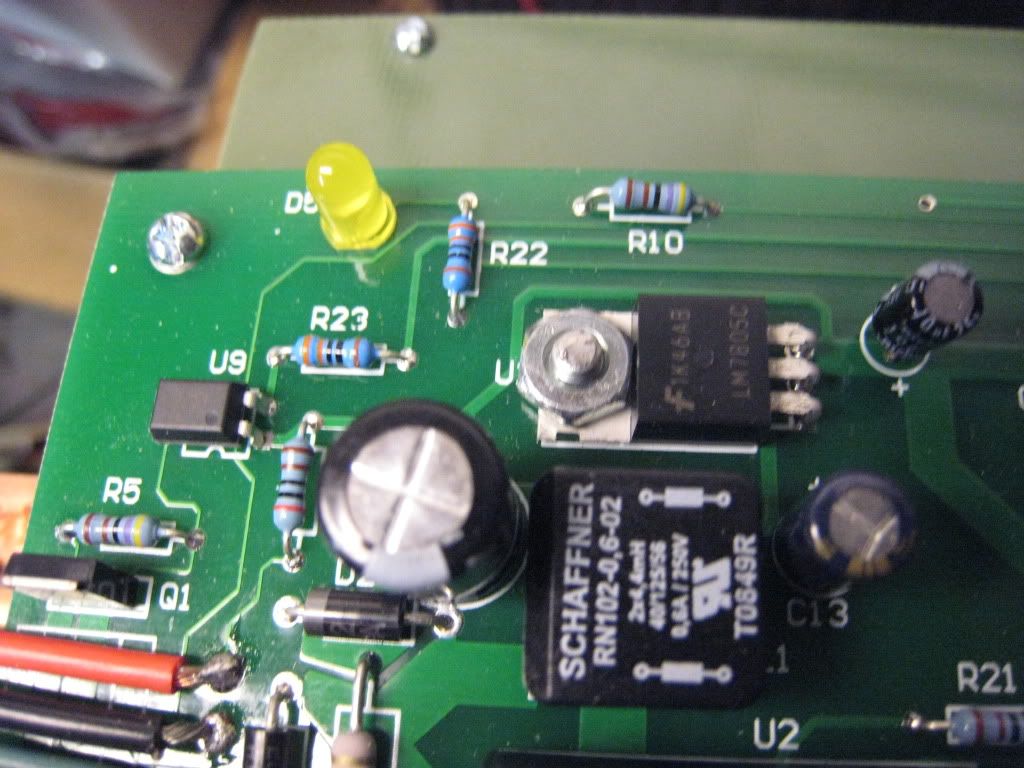
The opto is U9 and the transistor is Q1. If you have the board so your can read the writing, and the power connector on the left, U9's notch should be pointing downwards. The silver metal back of the transistor should be closest to the power wires.

Heres a picture.


The transistor is next to the white and yellow wires. The output on my controller is the brown wire, pin # 3. This is +12V when activated and shares a ground with pin # 2, the 12v battery negative that powers teh logic board.

See if any of this helps!!

-Adam

__________________
www.EVVette.com - 1971 Corvette Coupe Conversion to all Electric!
www.AdamBrunette.com - Machining, CNC, Robotics and Electronics.

You can download RTD Explorer for the Cougar controllers at www.EVVette.com
  Reply With Quote
Alt Today
Popular topics

Other popular topics in this forum...

   
Old 03-16-2010, 03:39 PM   #3192 (permalink)
EcoModding Lurker
 
Join Date: Dec 2009
Location: Long Beach Ca.
Posts: 50

E-car - '84 Toyota Corolla LE
Thanks: 3
Thanked 7 Times in 6 Posts
Adam, U9 and Q1 are correct on my board. Here's the pic.
  Reply With Quote
Old 03-16-2010, 04:32 PM   #3193 (permalink)
EcoModding Lurker
 
Join Date: Dec 2009
Location: Long Beach Ca.
Posts: 50

E-car - '84 Toyota Corolla LE
Thanks: 3
Thanked 7 Times in 6 Posts
Adam, I'll have to check different areas of the control board to determine where I'm loosing the signal. One thing is: when I made my final power connections to my controller I followed the schematic 1-5 although I felt the order was the other way 5-1 around. The wires you see in the picture were according to the schematic and I did put +12v into the board. Can "U9" handle that kind of abuse? Work is looming on the horizon so I may have to come back tomorrow for more fun.

Thanks for your help.

Mike
  Reply With Quote
Old 03-16-2010, 06:36 PM   #3194 (permalink)
Master EcoModder
 
jackbauer's Avatar
 
Join Date: Sep 2009
Location: Ireland
Posts: 734
Thanks: 26
Thanked 304 Times in 171 Posts
One thing i've been thinking about is a brake signal input to the controller. Perhaps just a 0v , 5v on an unused icsp pin. Similar setup to the "safety code" that paul wrote but if it sees the brake signal applied it automatically commands zero pwm. If after zero pwn is achieved it sees power flowing to the motor it open the main contactor. thoughts?
__________________
Now, Cole, when you shift the gear and that little needle on the ammeter goes into the red and reads 2000 Amps, that's bad.
www.evbmw.com
  Reply With Quote
Old 03-16-2010, 07:18 PM   #3195 (permalink)
EcoModding Apprentice
 
dave koller's Avatar
 
Join Date: Feb 2010
Location: Northern Wisconsin
Posts: 137
Thanks: 32
Thanked 39 Times in 23 Posts
Quote:
Originally Posted by jackbauer View Post
One thing i've been thinking about is a brake signal input to the controller. Perhaps just a 0v , 5v on an unused icsp pin. Similar setup to the "safety code" that paul wrote but if it sees the brake signal applied it automatically commands zero pwm. If after zero pwn is achieved it sees power flowing to the motor it open the main contactor. thoughts?
I want to do that in my version2 - If I don't build the controller or go to AC I still will have it at least "Looking at the PWM (on whatever) " and that would be a start Jack.. It is so much easier to do things in software
__________________
Dave ...
  Reply With Quote
Old 03-16-2010, 09:50 PM   #3196 (permalink)
Master EcoModder
 
Join Date: Apr 2009
Location: Charlton MA, USA
Posts: 463

EVVette - '71 Chevy Corvette Coupe
Thanks: 31
Thanked 183 Times in 94 Posts
Quote:
Originally Posted by jackbauer View Post
One thing i've been thinking about is a brake signal input to the controller. Perhaps just a 0v , 5v on an unused icsp pin. Similar setup to the "safety code" that paul wrote but if it sees the brake signal applied it automatically commands zero pwm. If after zero pwn is achieved it sees power flowing to the motor it open the main contactor. thoughts?
This is something that I was planing for the expansion board. The problem is if the code is added for the isp port, it will make it more difficult to add the expansion board.

-Adam
__________________
www.EVVette.com - 1971 Corvette Coupe Conversion to all Electric!
www.AdamBrunette.com - Machining, CNC, Robotics and Electronics.

You can download RTD Explorer for the Cougar controllers at www.EVVette.com
  Reply With Quote
Old 03-16-2010, 10:22 PM   #3197 (permalink)
EcoModding Apprentice
 
dave koller's Avatar
 
Join Date: Feb 2010
Location: Northern Wisconsin
Posts: 137
Thanks: 32
Thanked 39 Times in 23 Posts
Quote:
Originally Posted by adamj12b View Post
This is something that I was planing for the expansion board.
-Adam
Smart thinking Adam..
__________________
Dave ...
  Reply With Quote
Old 03-17-2010, 04:26 AM   #3198 (permalink)
PaulH
 
MPaulHolmes's Avatar
 
Join Date: Feb 2008
Location: Maricopa, AZ (sort of. Actually outside of town)
Posts: 3,832

Michael's Electric Beetle - '71 Volkswagen Superbeetle 500000
Thanks: 1,362
Thanked 1,202 Times in 765 Posts
Hi Flatman! I done figured it out! oh ya. You have to change the precharge wait time to greater than 0. The default is 0. Try maybe 30 or 60 or something. That would be 3 to 6 seconds of delay before the controller would close the contactor.

with the serial hooked up, type "config"
That will show all the current variable settings.

Now type:
pc-time 40
save

That will set the precharge time to 4 seconds. Then it will save it to eeprom. Now turn off the controller and on again, and the main contactor will close after 4 seconds.
__________________
kits and boards
  Reply With Quote
Old 03-17-2010, 05:04 AM   #3199 (permalink)
EcoModding Apprentice
 
dave koller's Avatar
 
Join Date: Feb 2010
Location: Northern Wisconsin
Posts: 137
Thanks: 32
Thanked 39 Times in 23 Posts
Quote:
Originally Posted by MPaulHolmes View Post
Hi Flatman! I done figured it out! oh ya.
Paul Today, 03:26 AM

LOL you don't sleep either - I was coding too...
__________________
Dave ...
  Reply With Quote
Old 03-17-2010, 07:50 AM   #3200 (permalink)
Master EcoModder
 
jackbauer's Avatar
 
Join Date: Sep 2009
Location: Ireland
Posts: 734
Thanks: 26
Thanked 304 Times in 171 Posts
Hey Paul , I don't suppose you had a chance to mail me that new control board? I got a bunch of free dspic samples last week so i'm keen to give it a try. My main interest is in making an all in one controller for the compound motor. If you need some money its no probs.

__________________
Now, Cole, when you shift the gear and that little needle on the ammeter goes into the red and reads 2000 Amps, that's bad.
www.evbmw.com
  Reply With Quote
Reply  Post New Thread


Similar Threads
Thread Thread Starter Forum Replies Last Post
Paul and Sabrina's Cheap 3 Phase Inverter (AC Controller) with Field Oriented Control MPaulHolmes Fossil Fuel Free 3431 05-04-2022 05:43 PM
Paul & Sabrina's Cheap EV Conversion MPaulHolmes Fossil Fuel Free 542 11-12-2016 09:09 PM
Three Dirt Cheap DIY Electric Cars - Part 5 SVOboy EcoModder Blog Discussion 0 12-12-2008 04:10 PM


Powered by vBulletin® Version 3.8.11
Copyright ©2000 - 2024, vBulletin Solutions Inc.
Content Relevant URLs by vBSEO 3.5.2
All content copyright EcoModder.com