Go Back   EcoModder Forum > EcoModding > Fossil Fuel Free > Open ReVolt: open source DC motor controller
Register Now
 Register Now
 

Reply  Post New Thread
 
Submit Tools LinkBack Thread Tools
Old 11-30-2010, 07:23 AM   #4061 (permalink)
Master EcoModder
 
Join Date: Apr 2009
Location: Charlton MA, USA
Posts: 463

EVVette - '71 Chevy Corvette Coupe
Thanks: 31
Thanked 183 Times in 94 Posts
Quote:
Originally Posted by Grimm View Post
So, does this mean we'll see Paul's very own display system built into the next controller? Complete with spiffy graphics of lightning bolts and tires burning rubber on the controller control panel?

On the topic of displays, laptop displays have pretty weird and flimsy connectors and aren't exactly the best choice. At least the displays I've worked with. Benjamin J Heckendorn has used everything from PS1 travel screens to digital picture frames to dirt cheap off brand LCD monitors in his projects and just recently did a hack with a rotating laptop screen. If someone somewhere has found a way to use the cheap touchscreens from digital picture frames for other hacks that would be a great way to tinker with controller data and settings on the fly.
Touch screen picture frame??? Thats an awesome idea. It shouldnt be that hard to do.

-Adam

__________________
www.EVVette.com - 1971 Corvette Coupe Conversion to all Electric!
www.AdamBrunette.com - Machining, CNC, Robotics and Electronics.

You can download RTD Explorer for the Cougar controllers at www.EVVette.com
  Reply With Quote
Alt Today
Popular topics

Other popular topics in this forum...

   
Old 12-01-2010, 09:10 AM   #4062 (permalink)
Custom EV Builder...
 
Join Date: Jul 2009
Location: Ohio
Posts: 57
Thanks: 8
Thanked 1 Time in 1 Post
Quote:
Originally Posted by mrbigh View Post
Adam
Can you please put an add in the classified section to promote sales count?
Thank you
Do we have a classified posting on this yet? Just want to know where to send the payment.
Thanks guys.
  Reply With Quote
Old 12-01-2010, 12:22 PM   #4063 (permalink)
Master EcoModder
 
Join Date: Apr 2009
Location: Charlton MA, USA
Posts: 463

EVVette - '71 Chevy Corvette Coupe
Thanks: 31
Thanked 183 Times in 94 Posts
Quote:
Originally Posted by wakinyantanka View Post
Do we have a classified posting on this yet? Just want to know where to send the payment.
Thanks guys.
No, Not yet. Ive just been going through PM.

-Adam
__________________
www.EVVette.com - 1971 Corvette Coupe Conversion to all Electric!
www.AdamBrunette.com - Machining, CNC, Robotics and Electronics.

You can download RTD Explorer for the Cougar controllers at www.EVVette.com
  Reply With Quote
Old 12-02-2010, 08:22 AM   #4064 (permalink)
EcoModding Lurker
 
Join Date: Jan 2010
Location: US
Posts: 14
Thanks: 0
Thanked 0 Times in 0 Posts
Hey guys!
Can some one give me a quick run down on where we are with the 1000 amp controller?
  Reply With Quote
Old 12-02-2010, 11:03 AM   #4065 (permalink)
Master EcoModder
 
jackbauer's Avatar
 
Join Date: Sep 2009
Location: Ireland
Posts: 734
Thanks: 26
Thanked 304 Times in 171 Posts
Ok need some advice here. I'm building up the parts for a controller build for the bike. I had intended to use a series / parallel switching arrangement between the two motors but have decided instead to give each motor its own controller! What i'm aiming for is one power stage with two igbts per motor , shared B+M+ and B- busbars and two control boards.

So first problem is how to drive two boards from one throttle signal .............
__________________
Now, Cole, when you shift the gear and that little needle on the ammeter goes into the red and reads 2000 Amps, that's bad.
www.evbmw.com
  Reply With Quote
Old 12-02-2010, 12:56 PM   #4066 (permalink)
AC-DC enthusiast
 
mrbigh's Avatar
 
Join Date: Nov 2009
Location: Long Island, NY
Posts: 282

Dual-PWR PHEV - '04 Toyota Prius

Kopper - '79 Bradley Bradley GT-II
Thanks: 123
Thanked 54 Times in 37 Posts
Quote:
Originally Posted by jackbauer View Post
Ok need some advice here. I'm building up the parts for a controller build for the bike. I had intended to use a series / parallel switching arrangement between the two motors but have decided instead to give each motor its own controller! What i'm aiming for is one power stage with two igbts per motor , shared B+M+ and B- busbars and two control boards.

So first problem is how to drive two boards from one throttle signal .............
Hi Jackbauer
Sharing the 3 bus bars I think will not be the a great idea. Now having a common bat/motor + and bat- and individual motor - to each motor, will be the right approach.
Driving the control boards: I would use a single, above 5K and below 10K pot throttle signal to drive both boards together .
__________________
. .. .. . .......
Prius Absolutum Dominium . ..........KOPPER
PHEV conversion since Dec 2006.. . .... .Future EV
. . . . . . . .CALCars # 27. . . . . . . . . . ..on the works now !!
. . . . . . . . . . . . . . . . .. . ........
  Reply With Quote
Old 12-02-2010, 03:31 PM   #4067 (permalink)
Joe
 
Join Date: Feb 2009
Location: phx
Posts: 260
Thanks: 0
Thanked 48 Times in 38 Posts
Quote:
Originally Posted by jackbauer View Post
So first problem is how to drive two boards from one throttle signal .............
An idea:

looking at the schematic, R10, R8 and the throttle pot form a resistor divider and R4 and C15 form an RC filter in front of the ADC input.

So, maybe keep one board normal. On the 2nd board, leave out R8 and R10. Then, have both boards share pin 4 on J1 (the throttle input, which, looking at the schematic, leads right into the RC filter). The idea is that there's one resistor divider, but the signal is sent to each board each with their own RC filter circuit. I'm also assuming that each board shares the same ground, which it would if they're each run off of the same battery.
__________________
ReVolt AZ testing thread:

http://ecomodder.com/forum/showthrea...ting-9325.html
  Reply With Quote
Old 12-02-2010, 04:24 PM   #4068 (permalink)
EcoModding Lurker
 
Join Date: Nov 2009
Location: Scottish Borders, Scotland
Posts: 92
Thanks: 7
Thanked 33 Times in 16 Posts
4dsystems touch screen display.

Back to the topic of a touch screen graphic display. I have been looking at the products from 4D Systems, an Australian company, and today ordered one of these µLCD-32PT(GFX) - 4DGL Display Modules. I have mentioned this product before, so while I am waiting for it to arrive I thought I would start writing some code for it. They have an IDE, free to download, and the language is kind C like but optimized for doing tasks such as displaying graphics and parsing serial data strings, perfect for what is required for this project. The first goal is to read the real time data stream from the controller and display the information on the screen. I have a couple of questions about the data stream.

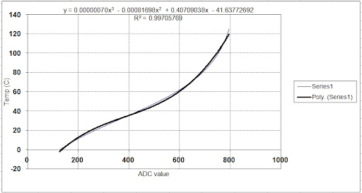
First, what is the formula to convert the temperature data to Celsius and Fahrenheit. Second has to do with the fault bits. I found this in the cougar.h file, but can't work it out.

Code:
#define THROTTLE_FAULT (1 << 0)
#define VREF_FAULT (1 << 1)
#define PRECHARGE_WAIT (1 << 5)
#define MOTOR_OS_FAULT (1 << 6)
#define HPL_FAULT (1 << 7)
So what is the values for the above faults, and can the controller set multiple faults at the same time?

I will post the code as and when I get something cobbled together. The next goal will be to have an interface to change controller settings. Another idea is to have a programmable preset memory like a car radio has. Maybe have 3 possible settings, say economy, normal and sport. Just press a button and the controller can be updated with the new settings. Also could be useful for testing new settings, you can save your current setting and always be able to revert back at the touch of a button.
  Reply With Quote
Old 12-02-2010, 04:43 PM   #4069 (permalink)
Joe
 
Join Date: Feb 2009
Location: phx
Posts: 260
Thanks: 0
Thanked 48 Times in 38 Posts
Quote:
Originally Posted by Greg Fordyce View Post
First, what is the formula to convert the temperature data to Celsius and Fahrenheit.
A while back I was curious about this and plotted it up using the circuit and values from the datasheet. Excel does curve fits pretty easily, and it looked somewhat 3rd order (I was hoping it was linear...)


I know Adam (or Paul?) made a look up table also - maybe they could check that equation against the table? Unless it's totally wrong, it looks like everything should be within a degree or two.
__________________
ReVolt AZ testing thread:

http://ecomodder.com/forum/showthrea...ting-9325.html
  Reply With Quote
The Following User Says Thank You to jyanof For This Useful Post:
Greg Fordyce (12-02-2010)
Old 12-02-2010, 05:44 PM   #4070 (permalink)
EcoModding Lurker
 
Join Date: Nov 2009
Location: Scottish Borders, Scotland
Posts: 92
Thanks: 7
Thanked 33 Times in 16 Posts
Thanks Joe, that graph will get me started on a simple lookup table. If someone has a lookup table maybe they could post it?

Greg

  Reply With Quote
Reply  Post New Thread


Similar Threads
Thread Thread Starter Forum Replies Last Post
Paul and Sabrina's Cheap 3 Phase Inverter (AC Controller) with Field Oriented Control MPaulHolmes Fossil Fuel Free 3480 05-04-2022 05:43 PM
Paul & Sabrina's Cheap EV Conversion MPaulHolmes Fossil Fuel Free 542 11-12-2016 09:09 PM
Three Dirt Cheap DIY Electric Cars - Part 5 SVOboy EcoModder Blog Discussion 0 12-12-2008 04:10 PM


Powered by vBulletin® Version 3.8.11
Copyright ©2000 - 2024, vBulletin Solutions Inc.
Content Relevant URLs by vBSEO 3.5.2
All content copyright EcoModder.com