 12-17-2010, 08:55 AM
|
#4121 (permalink)
|
|
EcoModding Apprentice
Join Date: Nov 2010
Location: Annapolis
Posts: 159
Thanks: 0
Thanked 32 Times in 27 Posts
|
How are you monitoring voltages? Is the microcontroller on the traction voltage side? Or are you using an isolator?
Right now our controller is mixed, with an optoisolator before the gate driver but no isolation if we monitor traction voltages. The MCP3008 A/D converter I mentioned is so that we can put the traction voltage monitoring on its own A/D converter sitting behind a SPI isolator. Isolators such as the Si8441 are under $2 at Digikey, but are only available in SOIC surface mount packages. That's a hassle with our test setup, so isolation will have to wait until we do a circuit board for something else.
Our alternative was using an isolated CAN transceiver such as the TI ISO1050 and leaving the controller at traction voltage. But then we would need to add a body-side controller, with CAN, to send any of the switch information we might use in the future.
We expect to add brake, clutch, neutral, reverse, cruise control and force-idle (e.g. A/C compressor drive) as inputs, and drive the tachometer as a combined motor/battery current/power gauge. Sending that info over CAN might be better in the long run, but right now we don't trust the implementation enough to do more than non-critical reporting.
Last edited by DJBecker; 12-17-2010 at 09:00 AM..
|
|
|

|
 Today Today
|
|
|
|
 Other popular topics in this forum...
|
|
|
|
|
12-17-2010, 11:22 AM
|
#4122 (permalink)
|
|
EcoModding Lurker
Join Date: Jun 2010
Location: Madison, WI
Posts: 4
Thanks: 0
Thanked 0 Times in 0 Posts
|
Regarding SMT components, the reliability is much greater. As this controller becomes more popular, people will start to rely on a car built with it. It seems this board has matured to point where it makes sense to switch over. As an added bonus, the board size can shrink thus lowering costs and allowing a smaller enclosure. If the board dimensions are optimized to use the "standard" panel of the board supplier and left in a panel for the automated assembly of passives, the cost really begin to drop.
Even manually building an entire SMT assembly is not that bad. Passives can be tacked down with dots of epoxy. After the glue cures you can follow up with a fine tipped soldering iron. Another option is a syringe with solder paste and reflow the entire board with a toaster oven, heat lamp, or heat gun.
edit: I was going to espouse the virtue of an SMD microcontroller, but if I'm looking at the right data sheet, 0.8 mm pin pitch would be tricky to hand solder. I've seen it done, but not by me. Stick with the DIP.
I know its easier said than done, but I've worked in the prototype business for a few years and I have seen much more complex boards built by relatively low skill people with minimal equipment, i.e. tweezers and a hot plate.
JAK
|
|
|
|
|
12-17-2010, 01:21 PM
|
#4123 (permalink)
|
|
PaulH
Join Date: Feb 2008
Location: Maricopa, AZ (sort of. Actually outside of town)
Posts: 3,832
Thanks: 1,362
Thanked 1,202 Times in 765 Posts
|
Ya, soldering that tqfp44 package isn't easy. I did 8 of them once, and 7 worked. Still, I practically went blind doing it. I actually think soldering the other components is easier than through-hole. I put a tiny drop of solder flux on each component/pad and then just hold down the component with a toothpick and touch the pad with my soldering iron and it's done. Still, when they can just throw it in an oven, that's way better!
Here's a schematic of the voltage monitoring circuit. It's isolated with a linear isolator. It's also tested by my friend that made it and it works very well:
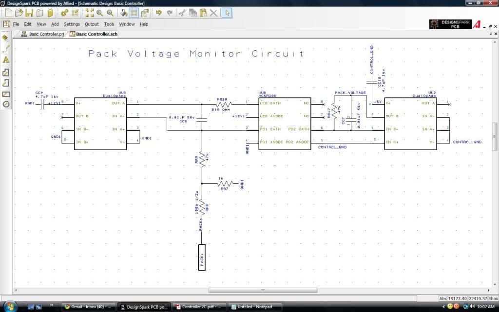
PACK_VOLTAGE is the net that is connected to an A/D pin on the microcontroller.
PACK+ is the hole where you solder a wire from the high voltage V+. GND1 is the high voltage ground. CONTROL_GND is the ground for the control, like the microcontroller. 12V1 is an isolated 12v supply that came from an isolated DC-DC. 12V1 shares it's ground with the high voltage battery pack.
Last edited by MPaulHolmes; 12-17-2010 at 04:07 PM..
|
|
|
|
|
12-17-2010, 02:31 PM
|
#4124 (permalink)
|
|
Master EcoModder
Join Date: Sep 2009
Location: Ireland
Posts: 734
Thanks: 26
Thanked 304 Times in 171 Posts
|
soooooo........when can i order 2 and how much are they? Is the pcb finished or could some "extras" be added?
oh and Jack Bauer does not solder 128 pin tqfp..........ever...... 
__________________
Now, Cole, when you shift the gear and that little needle on the ammeter goes into the red and reads 2000 Amps, that's bad.
www.evbmw.com
|
|
|
|
|
12-17-2010, 02:35 PM
|
#4125 (permalink)
|
|
PaulH
Join Date: Feb 2008
Location: Maricopa, AZ (sort of. Actually outside of town)
Posts: 3,832
Thanks: 1,362
Thanked 1,202 Times in 765 Posts
|
Oh, extras can ALWAYS be added! I got like friggen 200 free pins, yo.
|
|
|
|
|
12-17-2010, 02:38 PM
|
#4126 (permalink)
|
|
Master EcoModder
Join Date: Sep 2009
Location: Ireland
Posts: 734
Thanks: 26
Thanked 304 Times in 171 Posts
|
ok so could you add a little resistor and zener on a spare digital i/p line for rpm measurement and maybe another for a brake signal? Perhaps even track a few spare lines to solder pads to allow for experimintation.
__________________
Now, Cole, when you shift the gear and that little needle on the ammeter goes into the red and reads 2000 Amps, that's bad.
www.evbmw.com
|
|
|
|
|
12-17-2010, 02:39 PM
|
#4127 (permalink)
|
|
PaulH
Join Date: Feb 2008
Location: Maricopa, AZ (sort of. Actually outside of town)
Posts: 3,832
Thanks: 1,362
Thanked 1,202 Times in 765 Posts
|
Quote:
Originally Posted by jackbauer

ok so could you add a little resistor and zener on a spare digital i/p line for rpm measurement and maybe another for a brake signal? Perhaps even track a few spare lines to solder pads to allow for experimintation.
|
so let it be written... so let it be done.
Last edited by MPaulHolmes; 12-17-2010 at 04:00 PM..
|
|
|
|
|
12-17-2010, 05:07 PM
|
#4128 (permalink)
|
|
Computer/EV enthusiast
Join Date: Jan 2010
Location: Indiana, USA
Posts: 32
Thanks: 2
Thanked 7 Times in 5 Posts
|
That's some great news! Looking forward to when I can buy one.
Also, I don't know if this is very helpful, but I thought I'd pass it on. External RAM for an ATmega128 - Hack a Day |
|
|
|
|
12-17-2010, 11:33 PM
|
#4129 (permalink)
|
|
EcoModding Apprentice
Join Date: Nov 2010
Location: Annapolis
Posts: 159
Thanks: 0
Thanked 32 Times in 27 Posts
|
We are currently using a slot opto-interrupter to sense shaft rotation. The detector side is hooked directly up to an AVR pin with the internal pull-up (nominally 20K to 50K ohms) enabled -- no other input-side components were needed.
The signal disk is screwed to the front shaft of the motor. It's made of credit-card-like plastic that we rounded with a chisel after mounting. The "slot" is a round hole -- better than a notch to avoid snagging.
I didn't really expect it to work. We didn't characterize the device before using it, and the AVR's pull-ups are pretty loosely specified. But the scope showed a workable signal almost immediately. I think that we only needed a slight change of the LED drive resistor since it wasn't the same device I had tried on the breadboard.
The original plan was to paint a black-white pattern on the shaft coupler and use a reflective sensor rather than an interrupted slot. But this will do until we need the front shaft to drive the A/C compressor. (Note: Use white paint for reflection, since "silver" paint often absorbs IR light.)
Anyway, the point is that very little is needed for the RPM sensor. But you cannot add a feature like this later if you don't plan for it. You might have unused pins, but you can't use them if you do not have a way to get signals to the pins.
Our base controller board is the Mega 1280. It's great because it has a zillion I/O pins brought out on headers. But not quite all of them. We would like to use the analog comparator to trigger an interrupt on overcurrent, but that pin dead-ends. Only timer 4 and 5 have the count inputs and ICP pins brought out. And the clock output pin isn't available.
A little more about the the RPM measurements. We wired the opto-interrupter to a pin that is either general purpose I/O or the timer 5 capture pin. If we use the hardware timer, the implementation is surprisingly simple. The SIG_INPUT_CAPTURE5 handler just saves the hardware capture timestamp, puts the time since the last capture in a global variable, and clears the software-maintained overflow count. The TIMER5_OVF_vect handler increments the software overflow count, holding it at a saturated maximum so we don't lose track if the motor is turning too slowly (about 15RPM).
The slow part -- doing the division -- is only done when a function is called to requests the RPM. When we do that division we save the period and result so we don't have to needlessly recalculate.
Last edited by DJBecker; 12-18-2010 at 10:16 AM..
|
|
|
|
|
12-18-2010, 08:53 AM
|
#4130 (permalink)
|
|
EcoModding Lurker
Join Date: Oct 2009
Location: North Carolina
Posts: 41
Thanks: 23
Thanked 8 Times in 4 Posts
|

Hi everyone! I've been lurking and trying to read the whole post and am only half way through. But checked out the latest posts to see what's happening.
I noticed that Paul is going to a surface mount control board and read about having the processor soldered directly to the board and the comments on it being difficult to replace. I worked at IBM years ago and we used microscopes, tweezers and a fine tipped iron to remove and replace components with fine pitch leads. It's not impossible to do but does require magnification (although not on all parts).
I have a suggestion, if it's possible. Does the Microchip processor come in a PLCC package? If so, you could place the PLCC socket on the board and just plug the processor into it. Then, if it needed to be replaced you just pop it out and plug in the new one. It may be a pain to lay out the board again, but would be a decent solution. You could also do this for other IC's that may need to be replaced often. Don't do this for IC's you don't have trouble with. Just a suggestion....
Anyway, Paul and everyone else here, you should be proud of yourselves for what you have accomplished for the EV enthusiasts! Great job!!!!
Jim
|
|
|
|
|


