 02-13-2011, 10:06 PM
|
#101 (permalink)
|
|
Master EcoModder
Join Date: May 2008
Location: Maynard, MA Eaarth
Posts: 7,908
Thanks: 3,475
Thanked 2,953 Times in 1,846 Posts
|
Matt,
In the nit picking department, if the image you posted gets rotated 0.6d to the right (clockwise) than the ground line is level. 
|
|
|

|
 Today Today
|
|
|
|
 Other popular topics in this forum...
|
|
|
|
 02-13-2011, 11:22 PM
|
#102 (permalink)
|
|
T-100 Road Warrior
Join Date: Apr 2008
Location: The Woodlands, TX
Posts: 1,921
Thanks: 3,502
Thanked 1,395 Times in 968 Posts
|
Quote:
Originally Posted by cfg83

BamZipPow -
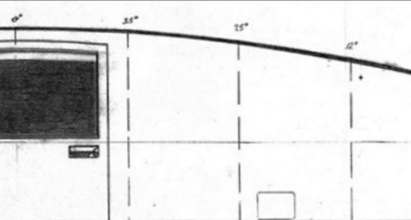
Nope, I'm not sure, it's the best I could read and cross-reference from the initial image. I can make a new one with those numbers.
CarloSW2
|
Well...I don't want you to believe what I say just because I said it. Here's a closeup...
|
|
|

|
 02-13-2011, 11:56 PM
|
#103 (permalink)
|
|
Master EcoModder
Join Date: Jan 2010
Location: Oregon
Posts: 471
Thanks: 15
Thanked 65 Times in 48 Posts
|
Looks to me like 0, 3.5, 7.5, and 12.
I decided to find a cheap car with a manual trans as a throwaway practice car, so I could learn how to drive a stick, and perhaps practice some hypermiling techniques, and resell it for parts if I break it, so I don't end up spending money on a good car and end up killing it. I put up an ad on Craigslist, and got an email back about a 1996 Ford Aspire 4 door for $700. I decided to check on how it would match the template.
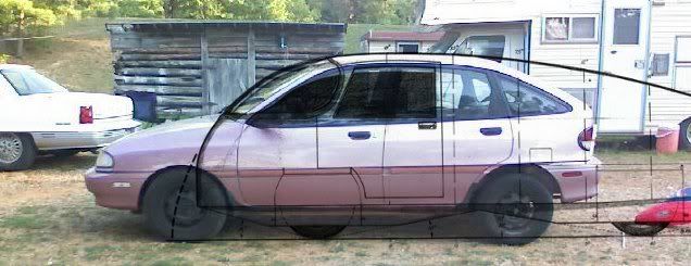
The rear hatch is obviously too steep, but the rest of the roof matches up pretty good. I think it might be a good candidate for a plexiglass kammback. And since it's OBD2, I'd be able to get a scangauge and actually test the effectiveness of different mods!
__________________
In Reason we Trust

|
|
|

|
 02-13-2011, 11:59 PM
|
#104 (permalink)
|
|
Master EcoModder
Join Date: May 2008
Location: Maynard, MA Eaarth
Posts: 7,908
Thanks: 3,475
Thanked 2,953 Times in 1,846 Posts
|
I've overlaid the ideal template with my CarBEN EV profile. Interesting.
By the way, the CarBEN EV uses 25" diameter tires (15" wheels) and the length of the template would be ~20+ feet; as the CarBEN EV is a bit less than 14' long.
|
|
|

|
|
The Following User Says Thank You to NeilBlanchard For This Useful Post:
|
|
 02-14-2011, 02:45 AM
|
#105 (permalink)
|
|
Pokémoderator
Join Date: Dec 2007
Location: Southern California
Posts: 5,864
Thanks: 439
Thanked 532 Times in 358 Posts
|
Neil -
Quote:
Originally Posted by NeilBlanchard

Matt,
In the nit picking department, if the image you posted gets rotated 0.6d to the right (clockwise) than the ground line is level.  |
I caught that and corrected it in my image. It wouldn't change the angles, though. The 0.6d error is in the scanning, not the creating.
CarloSW2 |
|
|

|
 02-14-2011, 04:09 AM
|
#106 (permalink)
|
|
T-100 Road Warrior
Join Date: Apr 2008
Location: The Woodlands, TX
Posts: 1,921
Thanks: 3,502
Thanked 1,395 Times in 968 Posts
|
Quote:
Originally Posted by AeroModder

And since it's OBD2, I'd be able to get a scangauge and actually test the effectiveness of different mods!
|
Have you thought about gitting the Ultra-Gauge instead of the ScangaugeII? It does offer a few more things that the SCII doesn't. However...the UG doesn't allow custom codes to be entered while the SCII does. Not sure that's gonna be a factor to yer purchase. The UG is about $70 while the SCII is about $150. Yer choice...  |
|
|

|
 02-14-2011, 10:00 AM
|
#107 (permalink)
|
|
(:
Join Date: Jan 2008
Location: up north
Posts: 12,762
Thanks: 1,585
Thanked 3,558 Times in 2,220 Posts
|
I found airfoils here: Airfoil Investigation Database - Showing NACA 0021
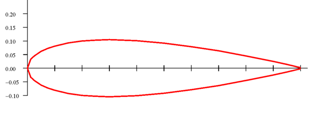
Then fattened the NACA 0021 profile 2x (that ground plane thing):
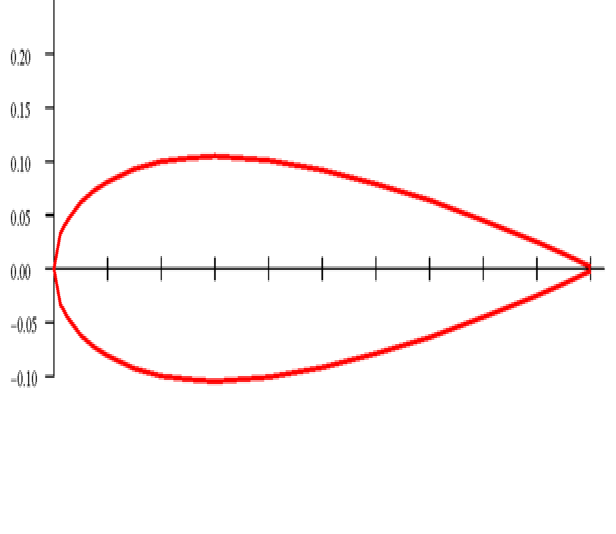
The NACA 0018 is listed as having somewhat lower drag vs the 0021; it appears they are the same shape only reproportioned e.g. 0018 is 18% as thick as it is long while the 0021 is 21% w/l. Here is the 0018 fattened 2x:
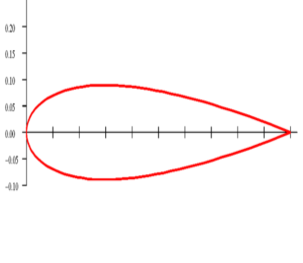
And they look like this template:
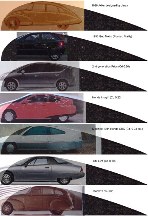
NOW, bear in mind that these airfoil profiles are 2-D. I came across this (slightly edited by me here):
Quote:
There's a difference between the flow around a two-dimensional cylinder and the flow around an axisymmetric form. The whole point of shaping an airfoil or a form is to manipulate the boundary layer through the pressure distribution along each surface streamline. Using an airfoil section for a 3-D form profile will not give you the design pressures or the desired boundary layer development.
Alex Strojnick, in his book, "Laminar Aircraft Technologies" (published by the author, now deceased), recommends taking airfoil coordinates to the 3/2 power (and scaling to the original thickness) to use them as templates for bodies of revolution. The result will be a more pointed shape than the corresponding 2D airfoil profile. For example, the figure below shows the NACA 66-021 section converted to an axisymmetric profile using Strojnick's technique. This resembles a Parson's low drag body shape, although Parson designed his bodies using a CFD analysis code and an optimization technique (Parson, J. S, Godson, R. E, Goldschmied, F.R., "Shaping of Axisymmetric Bodies for Minimum Drag in Incompressible Flow", Journal of Hydronautics, July 1967.)
The finest source of info on body shaping that I've seen is Bruce Carmichael's "Personal Aircraft Drag Reduction" (published by the author, 1995, mailto:brucecar1@juno.com; reviewed at http://www89.pair.com/techinfo/Books/bookrev.htm). Carmichael did pioneering research on low-drag bodies in water and came up with the Dolphin and SHAMU vehicle shapes. These bodies were designed in the 1960's for high speed towed sonar systems. It's possible to have quite low drag with bodies that have a fineness ratio as low as 3. There is extensive theoretical and experimental data on low drag bodies of several kinds presented in his book.
|
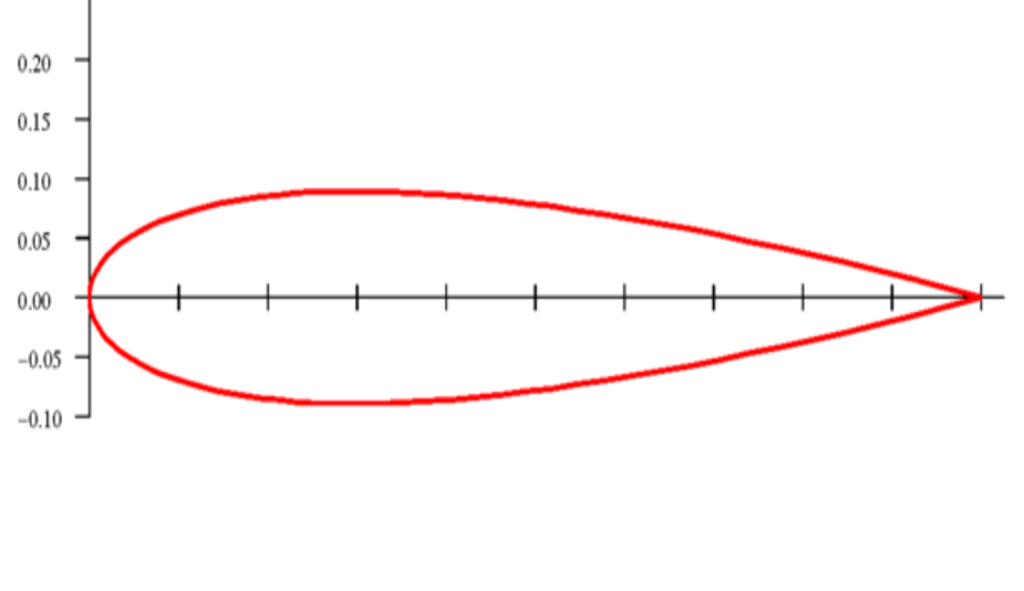
The NACA 0018 reproportioned as above:
Last edited by Frank Lee; 02-14-2011 at 10:47 AM..
|
|
|

|
 02-14-2011, 05:26 PM
|
#108 (permalink)
|
|
Master EcoModder
Join Date: Jan 2008
Location: Sanger,Texas,U.S.A.
Posts: 16,534
Thanks: 24,520
Thanked 7,436 Times in 4,817 Posts
|
template alignment
Quote:
Originally Posted by cfg83

RobertSmalls -
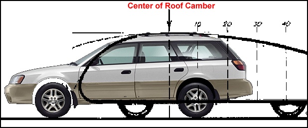
But isn't the apex or center of camber effected by where the downslope of the overlay touches the rear roofline of the car? :
I have been thinking that this would make a great Ecomodder iPhone app. The user provides a good side view of the car, inputs the ground and the apex of the car, let the app auto-scale the overlay, and then slide the overlay from side-to-side with your fingers.
I doubt there'd be any $ to be made, but it would be good advertising for EM.
CarloSW2 |
*The subject vehicle will have a point of maximum roof camber and that's a fixed point,it's not negotiable.
* The template has its zero-point or maximum roof camber and it's a fixed point and cannot be moved.
* If the two images are scaled such that the height of their max roof camber points are identical and then aligned together,this is the only condition in which the template can function.The template cannot function with any other alignment.
* If the roof of the subject vehicle conflicts with the template,it only indicates the aerodynamic compromise and we'll have to do the best with what we've got to work with.
|
|
|

|
|
The Following User Says Thank You to aerohead For This Useful Post:
|
|
 02-14-2011, 05:44 PM
|
#109 (permalink)
|
|
Master EcoModder
Join Date: Jan 2008
Location: Sanger,Texas,U.S.A.
Posts: 16,534
Thanks: 24,520
Thanked 7,436 Times in 4,817 Posts
|
fit
Quote:
Originally Posted by KamperBob

In the FWIW department, if I was trying to fit this template to a vehicle I might break it into 3 peices: one top and two bottoms. In addition to scaling height, users need to allow for wheelbase and overhang variations over a broad range of vehicles. The composite template looks cool, but the silhouette going to ground plane without wheels seems more mistake proof (poka-yoke to Toyota). Separate templates could be more useful. Members likely focus on one mod at a time anyway, so their visuals might be less confusing to others who miss dialog and take away wrong ideas from visuals. Food for thought?
|
The templates emphasis is on a vehicles aft-body,as this is where the lion's share of drag occurs.
Most contemporary automobiles have a
'good enough' fore-body,that good flow from there is assumed.
The template,as described in the first two portions of the thread,reduces the criteria for its use to a single element,height.That's all one needs to create an aft-body with zero separation.
--------------------------------------------------------------------------
The ground clearance of the template is in the spirit of all the other templates developed,from Jaray/Klemperer,to Kamm,Lay,R.G.S.White,and others.
--------------------------------------------------------------------------
The Approach,Departure,and Ramp Break-over angles are based solely on the tires and there position under the car.If any part of a vehicle goes below these projected angles,those parts will be knocked off the car at some point unless the car has active suspension,or the parts themselves are active.
That's all I'm trying to convey.Everyone will have to evaluate their vehicle on its own merits |
|
|

|
 02-14-2011, 05:49 PM
|
#110 (permalink)
|
|
Left Lane Ecodriver
Join Date: Aug 2008
Location: Buffalo, NY, USA
Posts: 2,257
Thanks: 79
Thanked 287 Times in 200 Posts
|
Quote:
Originally Posted by aerohead

*The subject vehicle will have a point of maximum roof camber and that's a fixed point,it's not negotiable.
* The template has its zero-point or maximum roof camber and it's a fixed point and cannot be moved.
* If the two images are scaled such that the height of their max roof camber points are identical and then aligned together,this is the only condition in which the template can function.The template cannot function with any other alignment.
* If the roof of the subject vehicle conflicts with the template,it only indicates the aerodynamic compromise and we'll have to do the best with what we've got to work with.
|
Phil,
Consider a bread truck. Any point along the roof of its box is equally valid as the point of maximum camber. A similar sad story goes for most full sized pickups.
If you were to slice the template vertically at the 0% mark and insert a rectangle (of any width), the drag coefficient would go up due to skin friction, but you could still use the template to guarantee attached flow, right? So a bread truck or a minivan with a boat tail grafted on the back would do okay, though not as well as the same treatment applied to a Prius.
|
|
|

|
|