Hi Guys,
I have been working over the past few weeks on getting ready to do high voltage testing on a small version of the controller. I have charged up 20 SLA 12V batteries and acquired a 130VDC 26A 2.65 HP treadmill motor and machined the small controller. I am going to start with 9 batteries and measure the voltage spikes and keep adding batteries till A: I reach 14 or 15 batteries, or B: I break the controller and call it as 1 less then what broke it.
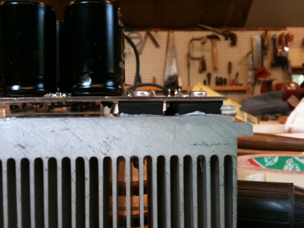
Some pictures of the test controller:
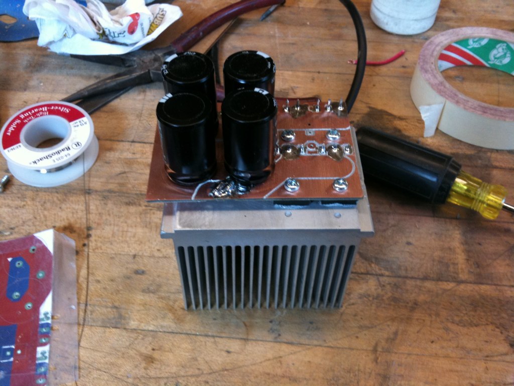

Mosfets and Diodes are on the bottom side clamped to the heat-sink through the PCB:
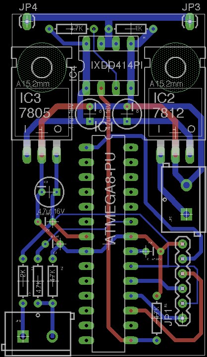
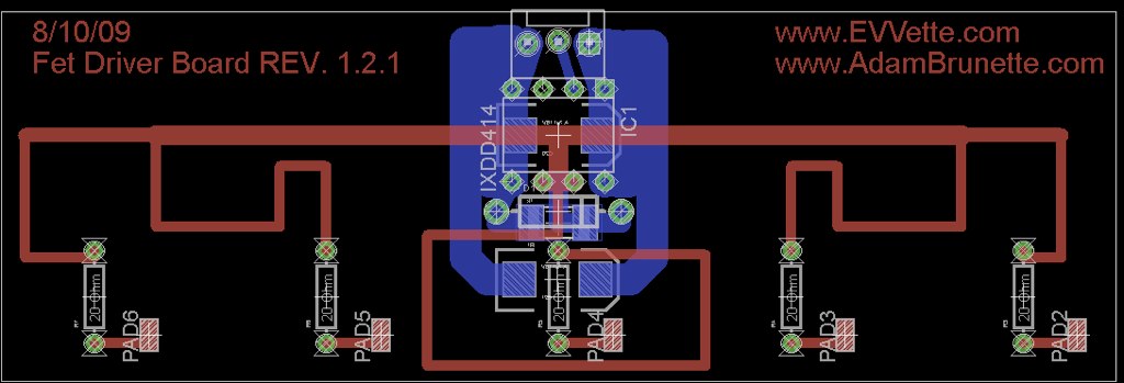
Test Control Board:
While I was designing the 2 pair test controller, I came across a very very good layout for the controller. I decided to see where I could take this design. I ended up with a recreation of Paul's controller on a more friendly layout. He seemed to really like the layout. It contained 10 pairs just like his, but only had 15 caps. Since he decided to go with the 820uf caps now this is not a problem being 1 down. It also has places to mount 2 of the poly spike suppression caps. And its just beautiful!!

The controller uses a slimed down version of the fet driver board that I designed for my controller. This one is 5 fets per driver down from 7.
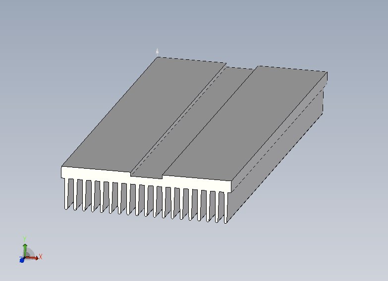
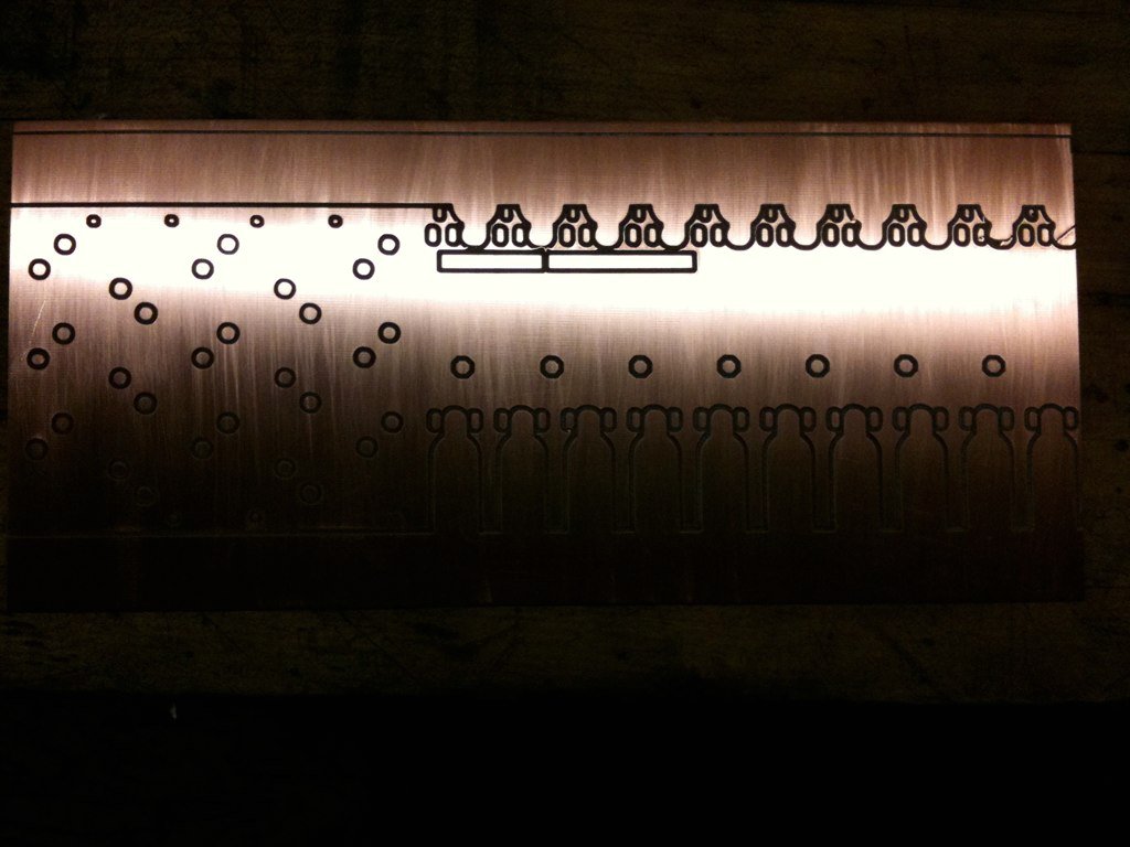
This controller is set up like the test stand where the PCB is the top clamp for holding the mosfets and diodes to the heat-sink. The heatsink I plan on using is from
HeatsinkUSA.com. It is the small size they offer. It should be a perfect size for the controller. The PCB is 12" long and 5.3" wide and the heat-sink is 12" long and 5.375" wide. With a small aluminum box around the bottom of the heat-sink it would be perfect. The heat-sink will have a channel milled down the middle to allow room for the M- buss bar. The 3 buss bars will be 1/4" thick by 3/4" wide. Should be heavy enough for a continuous 600A. I will also drill and tap all 20 holes for the mosfets and diodes. The heat-sink could be made to only the length of the mosfet/diode section with just regular sheet metal over the rest, or it could just be the entire length of the controller. What do you guys think?

Now for the bad news....I dont have money to build this controller.

It might be awhile before you will see one, but I plan on building one for my golf cart. I have the PCB, but it ends there for materials.
If anybody is interested in funding the building of one of these, I will build it for you and send it off for you to beat on.

Just get ahold of me. Paul would love to see this power section in action, but wants somebody to test it first. Once it gets the all clear, we will make a bunch more.
I hope to start enlarging it, Im thinking 15 pairs and 24 caps. it will make the controller about 7-8" longer for a total of about 18" and 5.5" wide. Long and Skinny.
Please let me know what you guys think.
-Adam


 ). Also, I think a FAQ would be fantastic for your sig, to preemptively answer a lot of the questions people raise. If I were to start one, could you link to that as well?

 Today
Today