Go Back   EcoModder Forum > EcoModding > Fossil Fuel Free > Open ReVolt: open source DC motor controller
Register Now
 Register Now
 

Reply  Post New Thread
 
Submit Tools LinkBack Thread Tools
Old 05-28-2012, 06:17 PM   #5751 (permalink)
EcoModding Apprentice
 
Join Date: Mar 2011
Location: alaska
Posts: 141
Thanks: 10
Thanked 37 Times in 19 Posts
i don't think it's ever been socketed before....it's a good piece and the board has protection in it so there's a resistor that will burn out before the converter. the only problem i know of with the converter is sometimes soldering it to the ground plane can be hard, but i think that's been fixed since then.

  Reply With Quote
The Following User Says Thank You to isaac_alaska For This Useful Post:
electricstorm (05-28-2012)
Alt Today
Popular topics

Other popular topics in this forum...

   
Old 05-28-2012, 06:26 PM   #5752 (permalink)
EV Connoisseur
 
Join Date: Aug 2010
Location: Amsterdam
Posts: 309
Thanks: 70
Thanked 109 Times in 90 Posts
I'd say that socketing may cause more problems because of resonance and bad connections.

You can always desolder a component if it fails..
  Reply With Quote
Old 05-28-2012, 08:25 PM   #5753 (permalink)
EcoModding Apprentice
 
apowers's Avatar
 
Join Date: Aug 2009
Location: Tn
Posts: 126
Thanks: 14
Thanked 19 Times in 16 Posts
I have not had any problem with mine. One board is in a controller since 09, and another was in a charger. The one in the charger would run 8 to 10 hours a day for over a year not counting winter months. The control board still works but is just not being used now.

I used sockets almost everywhere too.

Alvin
  Reply With Quote
Old 05-28-2012, 08:28 PM   #5754 (permalink)
EcoModding Lurker
 
Join Date: Apr 2009
Location: Mauston, WI
Posts: 20
Thanks: 1
Thanked 8 Times in 7 Posts
I socketed all the IC's but not the Cincon. Everything's running fine!
  Reply With Quote
Old 05-29-2012, 07:31 PM   #5755 (permalink)
EcoModding Lurker
 
Join Date: Oct 2009
Location: North Carolina
Posts: 41
Thanks: 23
Thanked 8 Times in 4 Posts
Thanks everyone for the response.

I was mainly concerned with having to replace the Cincon should it happen to fail. But it sounds like no one has had a failure so I guess I'll go ahead and solder it in.

One other question. Can the control board be tested without the power board as far as using a scope and checking signals? Or is it best to have the whole unit assembled before testing?

Planning on doing some checking of the circuit and then completing the power board, assembling and testing with an old starter as a first load test.

Jim
  Reply With Quote
Old 05-30-2012, 12:21 AM   #5756 (permalink)
EV Connoisseur
 
Join Date: Aug 2010
Location: Amsterdam
Posts: 309
Thanks: 70
Thanked 109 Times in 90 Posts
Yes. You can test the controlboard seperately with a scope.
  Reply With Quote
Old 05-30-2012, 12:48 PM   #5757 (permalink)
Joe
 
Join Date: Feb 2009
Location: phx
Posts: 260
Thanks: 0
Thanked 48 Times in 38 Posts
Quote:
Originally Posted by electricstorm View Post
Thanks everyone for the response.

I was mainly concerned with having to replace the Cincon should it happen to fail. But it sounds like no one has had a failure so I guess I'll go ahead and solder it in.

One other question. Can the control board be tested without the power board as far as using a scope and checking signals? Or is it best to have the whole unit assembled before testing?

Planning on doing some checking of the circuit and then completing the power board, assembling and testing with an old starter as a first load test.

Jim
for testing, i think you'll just have to hook up the current sensor. also, without any current actually flowing, the controller will just go to full on in an attempt to increase the output current. maybe if you use a really low kp and ki, you'll be able to see the transition between off and on, but i guess if it goes on and off, that means it's working.

as for desoldering, i'd recommend one of these. I've had nothing but success with mine and it's very affordable at $12.

RadioShack® 45-Watt Desoldering Iron - RadioShack.com
__________________
ReVolt AZ testing thread:

http://ecomodder.com/forum/showthrea...ting-9325.html
  Reply With Quote
The Following 2 Users Say Thank You to jyanof For This Useful Post:
electricstorm (05-31-2012), MPaulHolmes (05-31-2012)
Old 05-31-2012, 09:28 AM   #5758 (permalink)
PaulH
 
MPaulHolmes's Avatar
 
Join Date: Feb 2008
Location: Maricopa, AZ (sort of. Actually outside of town)
Posts: 3,832

Michael's Electric Beetle - '71 Volkswagen Superbeetle 500000
Thanks: 1,368
Thanked 1,202 Times in 765 Posts
I practiced different solder techniques yesterday for the TO-247 package backs to bus bars. I put a sample of paste on the Middle leg (it's connected to the back), and then put the component on a bar that is around 450-500 degF. It takes 5 seconds for the middle leg to melt the solder, and then I give it 5 seconds in melted state and then put it in a water bath. It cools in just a couple seconds. Here's some soldering of one of the phases of the AC controller (by the way, the skinny area in the middle is where the current sensor goes. Skinnier makes the current sensor more sensitive.:


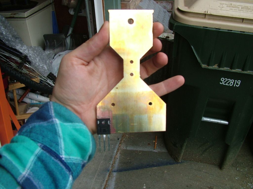
That's going to actually be 4 igbts per phase later, but just one free (Thanks Rod Hower!!!) 50amp igbt per phase for testing.

I also ordered a 48 pound 200amp inductor that I'm going to use with testing the controller. I know I know, some resistance also needs to be added to increase the PWM duty and not just test the freewheel diode! haha. I have that covered too. This move proved necessary since my crappy motor threw some bars that the brushes rub against when it ran full tilt at around 120v. It was also rated for 24v. Man, that was friggen scary. Long story, must go to school!
__________________
kits and boards
  Reply With Quote
Old 05-31-2012, 12:50 PM   #5759 (permalink)
EcoModding Lurker
 
Join Date: Feb 2009
Location: Arizona
Posts: 3
Thanks: 0
Thanked 2 Times in 1 Post
Quote:
Originally Posted by electricstorm View Post
Can the control board be tested without the power board as far as using a scope and checking signals? Or is it best to have the whole unit assembled before testing?
Electricstorm,
if you clip your oscope ground to the top of R17 (FET ground), and attach the signal probe to pin 7 of U7, you should be able to see the 12v PWM trace with period of about 60usec (~16kHz). I also set ki=20 (down from 160) to slow the pwm rise time in order to see the duty cycle changes more clearly. This can be done without the power board attached.
  Reply With Quote
The Following 2 Users Say Thank You to foor For This Useful Post:
electricstorm (05-31-2012), MPaulHolmes (05-31-2012)
Old 06-04-2012, 04:09 PM   #5760 (permalink)
EcoModding Noob
 
twotires's Avatar
 
Join Date: Dec 2010
Location: Raleigh, NC, USA
Posts: 24
Thanks: 9
Thanked 4 Times in 3 Posts
Electricstorm,
You can also build a quick voltage divider from 1/4W resistors to fool the control board into believing it's getting a signal back from the current sensor - keeps you from getting the yellow light - then scope the signals at U7 ....

Michael

  Reply With Quote
Reply  Post New Thread


Similar Threads
Thread Thread Starter Forum Replies Last Post
Paul and Sabrina's Cheap 3 Phase Inverter (AC Controller) with Field Oriented Control MPaulHolmes Fossil Fuel Free 3480 05-04-2022 05:43 PM
Paul & Sabrina's Cheap EV Conversion MPaulHolmes Fossil Fuel Free 542 11-12-2016 09:09 PM
Three Dirt Cheap DIY Electric Cars - Part 5 SVOboy EcoModder Blog Discussion 0 12-12-2008 04:10 PM


Powered by vBulletin® Version 3.8.11
Copyright ©2000 - 2024, vBulletin Solutions Inc.
Content Relevant URLs by vBSEO 3.5.2
All content copyright EcoModder.com