Go Back   EcoModder Forum > EcoModding > Fossil Fuel Free > Open ReVolt: open source DC motor controller
Register Now
 Register Now
 

Reply  Post New Thread
 
Submit Tools LinkBack Thread Tools
Old 03-05-2015, 01:22 AM   #7011 (permalink)
EcoModding Lurker
 
Join Date: Dec 2014
Location: Ohio
Posts: 15
Thanks: 7
Thanked 23 Times in 12 Posts
Alright, one more post and I can add pictures:

What did the father buffalo say to the son buffalo when he left for work?

Bison

  Reply With Quote
The Following User Says Thank You to Bela For This Useful Post:
MPaulHolmes (03-05-2015)
Alt Today
Popular topics

Other popular topics in this forum...

   
Old 03-05-2015, 01:40 AM   #7012 (permalink)
EcoModding Lurker
 
Join Date: Dec 2014
Location: Ohio
Posts: 15
Thanks: 7
Thanked 23 Times in 12 Posts
Well I think my post count is high enough that I can add pictures. The pictures show the base plate with most of the parts arranged although since the picture was taken I decided to use a smaller relay for precharging instead of the GX12.


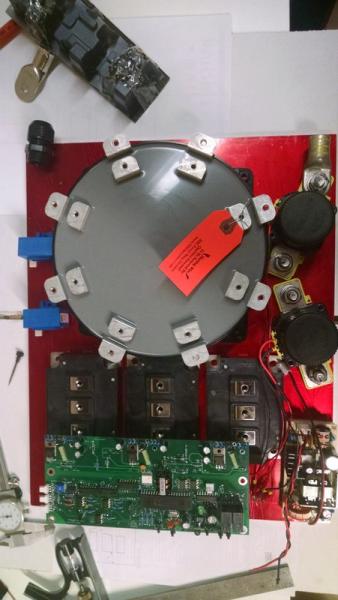
The picture with the copper plates show the precharger relay and a second relay for controlling a cooling pump.


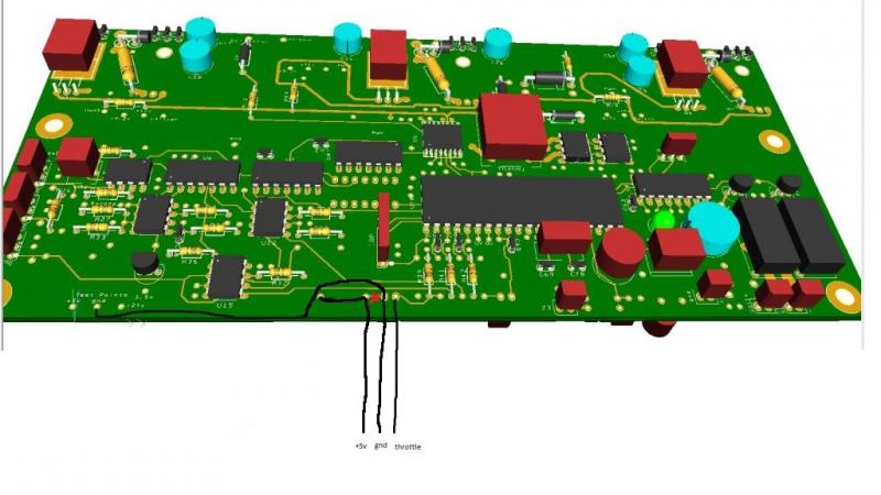
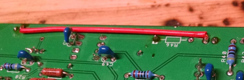
One problem I had was that my base plate isn't long enough so I had to overlap the Open Revolt board with the IGBTs. To do this I bent some wires that go from the high voltage side of the control board to the igbt connectors. I don't have any experience with EMF, especially at these voltages and currents so I hope this works OK.


On the bright side, by elevating the controller board, I have room under it for a raspberry pi and for a new board with some voltage monitoring logic for battery and motor voltage. More details to come when I actually get the board working.

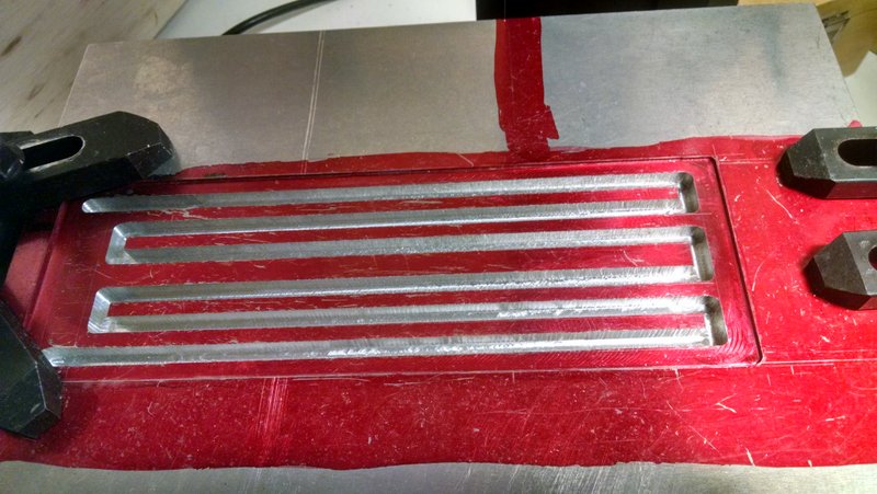
The base plate is 1/2 inch aluminum which was thick enough to allow for cooling grooves to be cut directly into it. Thanks goes to Micah and his electric porsche blog for the idea.


Hopefully in a couple weeks I can post a finished controller!
  Reply With Quote
The Following 3 Users Say Thank You to Bela For This Useful Post:
64jeep (03-05-2015), jedsmd (03-05-2015), MPaulHolmes (03-05-2015)
Old 03-05-2015, 02:00 AM   #7013 (permalink)
EcoModding Lurker
 
Join Date: Jan 2012
Location: Gilbert AZ
Posts: 20
Thanks: 1
Thanked 17 Times in 8 Posts
Hey, nice looking water plate! The rest of the controller looks good too. I'm just surprised to hear someone read my blog!
__________________
Electric Porsche 924 Converted using an IGBT based Paul and Sabrina Controller
electricporsche924.blogspot.com
  Reply With Quote
The Following 2 Users Say Thank You to 64jeep For This Useful Post:
Bela (03-05-2015), MPaulHolmes (03-05-2015)
Old 03-16-2015, 05:27 PM   #7014 (permalink)
EcoModding Lurker
 
Join Date: Dec 2014
Location: Ohio
Posts: 15
Thanks: 7
Thanked 23 Times in 12 Posts
Would the following modification work for using a hall effect throttle controller? It is hard to see in the picture but the idea is to cut the trace where the red X is (looks like a red blob on this picture) and then swap +5 and Gnd as compared to Paul's original picture. Doing this would make my pinouts a little cleaner.

Looking at the schematic it looks like if the resister R46 was removed then the 2 pads for +5 and gnd would not be connected to anything so their polarity wouldn't matter.
  Reply With Quote
The Following User Says Thank You to Bela For This Useful Post:
MPaulHolmes (03-19-2015)
Old 03-19-2015, 01:13 PM   #7015 (permalink)
PaulH
 
MPaulHolmes's Avatar
 
Join Date: Feb 2008
Location: Maricopa, AZ (sort of. Actually outside of town)
Posts: 3,832

Michael's Electric Beetle - '71 Volkswagen Superbeetle 500000
Thanks: 1,368
Thanked 1,202 Times in 765 Posts
I'm a little confused. If you get rid of R46, you can use the left pad of R46 for 5v. Ground must have a connection on the board that's connected to the ground plane. I'm having trouble seeing how you are getting a ground connection on the board by doing what you are suggesting.
__________________
kits and boards
  Reply With Quote
Old 03-19-2015, 03:47 PM   #7016 (permalink)
EcoModding Lurker
 
Join Date: Dec 2014
Location: Ohio
Posts: 15
Thanks: 7
Thanked 23 Times in 12 Posts
The idea is to run a wire from the test point GND to the left pad of jumper J1. Then cut the trace between the J1 left pad and the R46 right pad. Then get 5V from the right pad of R46.

It sounds messy but would allow me to put a 3 pin connector on the board for connecting to the hall effect throttle.

Hope this is right because I already made the changes! Here are some pictures to help clarify.

Before powering on the board I wanted to double check that the J1 left pad is not connected to anything once the trace is cut.

Here is the ground wire:


And the 5V wire (The bottom of the left most pin on the 3 pin connector is bent and soldered to the red wire):
  Reply With Quote
The Following User Says Thank You to Bela For This Useful Post:
MPaulHolmes (03-19-2015)
Old 03-19-2015, 04:22 PM   #7017 (permalink)
PaulH
 
MPaulHolmes's Avatar
 
Join Date: Feb 2008
Location: Maricopa, AZ (sort of. Actually outside of town)
Posts: 3,832

Michael's Electric Beetle - '71 Volkswagen Superbeetle 500000
Thanks: 1,368
Thanked 1,202 Times in 765 Posts
Oh! yes!
__________________
kits and boards
  Reply With Quote
The Following User Says Thank You to MPaulHolmes For This Useful Post:
Bela (03-19-2015)
Old 04-10-2015, 05:40 AM   #7018 (permalink)
EcoModding Lurker
 
Join Date: Apr 2015
Location: USA
Posts: 12
Thanks: 5
Thanked 4 Times in 3 Posts
Just put together the controller board. Is it testable without the powerboard? Right now I have controller board, 0-5K pot, and current sensor plugged in. My PWM output at R17 is flatline. The PWM signal on pin15 of the Atmega 168 is also flatline 0V. I've gone through and checked the supply voltages at the 6W converter, the 12V in, and the LM7805. All are correct voltages at 12V and 5V for the latter.

Also I am getting errors trying to download RTD explorer. Says something about not being able to find bobert...Can anyone help?

Thanks!
  Reply With Quote
Old 04-10-2015, 05:49 AM   #7019 (permalink)
EcoModding Lurker
 
Join Date: Apr 2015
Location: USA
Posts: 12
Thanks: 5
Thanked 4 Times in 3 Posts
I also just get a solid green light. Yellow LED does not come on.
  Reply With Quote
Old 04-11-2015, 12:57 PM   #7020 (permalink)
PLUGnGO
 
jedsmd's Avatar
 
Join Date: Sep 2012
Location: Olympia Wa
Posts: 137
Thanks: 75
Thanked 82 Times in 54 Posts
Quote:
Originally Posted by Articus View Post
Just put together the controller board. Is it testable without the powerboard? Right now I have controller board, 0-5K pot, and current sensor plugged in. My PWM output at R17 is flatline. The PWM signal on pin15 of the Atmega 168 is also flatline 0V. I've gone through and checked the supply voltages at the 6W converter, the 12V in, and the LM7805. All are correct voltages at 12V and 5V for the latter.

Also I am getting errors trying to download RTD explorer. Says something about not being able to find bobert...Can anyone help?

Thanks!
Are you using a preprogramed chip from Paul? If not, have you successfully loaded the unified firmware?

Index of /firmware/cougar-v1.11b/hexfiles-m168

Also when loading firmware for the first time the fusebits need to be set, see mora's post:

http://ecomodder.com/forum/showthrea...tml#post399312


Last edited by jedsmd; 04-11-2015 at 01:48 PM..
  Reply With Quote
The Following User Says Thank You to jedsmd For This Useful Post:
Articus (04-12-2015)
Reply  Post New Thread


Thread Tools


Similar Threads
Thread Thread Starter Forum Replies Last Post
Paul and Sabrina's Cheap 3 Phase Inverter (AC Controller) with Field Oriented Control MPaulHolmes Fossil Fuel Free 3480 05-04-2022 05:43 PM
Paul & Sabrina's Cheap EV Conversion MPaulHolmes Fossil Fuel Free 542 11-12-2016 09:09 PM
Three Dirt Cheap DIY Electric Cars - Part 5 SVOboy EcoModder Blog Discussion 0 12-12-2008 04:10 PM


Powered by vBulletin® Version 3.8.11
Copyright ©2000 - 2024, vBulletin Solutions Inc.
Content Relevant URLs by vBSEO 3.5.2
All content copyright EcoModder.com