09-11-2013, 12:40 AM
|
#591 (permalink)
|
|
Master EcoModder
Join Date: Aug 2012
Location: northwest of normal
Posts: 29,427
Thanks: 8,370
Thanked 9,128 Times in 7,537 Posts
|
Now we're talkin'.
Having re-read the last page I'll just say Thee Template is a wingtip, on a wing of negligible span.
|
|
|

|
 Today Today
|
|
|
|
 Other popular topics in this forum...
|
|
|
|
|
09-11-2013, 03:54 PM
|
#592 (permalink)
|
|
Master EcoModder
Join Date: Jan 2008
Location: Sanger,Texas,U.S.A.
Posts: 16,534
Thanks: 24,520
Thanked 7,438 Times in 4,818 Posts
|
wingtip
Quote:
Originally Posted by freebeard

Now we're talkin'.
Having re-read the last page I'll just say Thee Template is a wingtip, on a wing of negligible span.
|
That's a good way to think about it.
Not too long back,Frank Lee posted a 20% thickness airfoil section that was delicious.
Anything with an aft-body contour like this will be well received by the boundary layer. 
__________________
Photobucket album: http://s1271.photobucket.com/albums/jj622/aerohead2/
|
|
|
|
|
09-12-2013, 08:51 AM
|
#593 (permalink)
|
|
Master EcoModder
Join Date: Jul 2011
Location: Ann Arbor, Michigan
Posts: 4,215
Thanks: 145
Thanked 2,827 Times in 1,983 Posts
|
Maybach - Paul Jaray e a aerodinâmica - Um olhar sobre as corridas
Quote:
"The ideal way Jaray applied to a body close to the ground" in 1920
ETH Library, History of Science Collection, Zurich, Switzerland
|
FIRST POSTED IN ANOTHER THREAD HERE:
http://ecomodder.com/forum/showthrea...d-26678-2.html
http://heinkelscooter.blogspot.com/2...oples-car.html
Quote:
An Idea Crystallises
The concept of the Volkswagen as we know it begins in 1920 with the patents of a Hungarian aeronautical engineer named Paul Jaray. Born in 1899 in Vienna, Paul Jaray studied aeronautics in Prague and wrote extensively on wing design and aeronautical theory. In 1914 he joined the Zeppelin Company and rose through the ranks to become their chief designer.
Jaray recognised the importance of aerodynamic streamlining, and although he couldn't put these ideas into practice during the war, he experimented extensively in Zeppelin's wind tunnels on a range of design concepts. After the Treaty of Versailles put an end to Germany's aircraft and airship industry, Jaray turned his interest to cars. In 1922 he lodged a patent for a car design concept featuring a "half stream-lined body shell" that would "reduce the resistance of air to the highest degree attainable" by "deflecting the air chiefly upwards, as well as rearwards over its top and then down to the bottom with the least disturbance as possible."
Another key design feature was the rear mounting of the engine, which maximised the use of interior space. The design concept was so radical and exciting that it attracted immediate interest from a range of companies. Jaray consulted for companies such as Hanomag, Adler, Mercedes-Benz, Maybach, Auto-Union, Tatra, Steyer-Puch and even Chrysler in the United States, before moving to Switzerland in the late 1920s and establishing his own consulting company called Stromlinen Karosserie (streamlined bodywork).
|


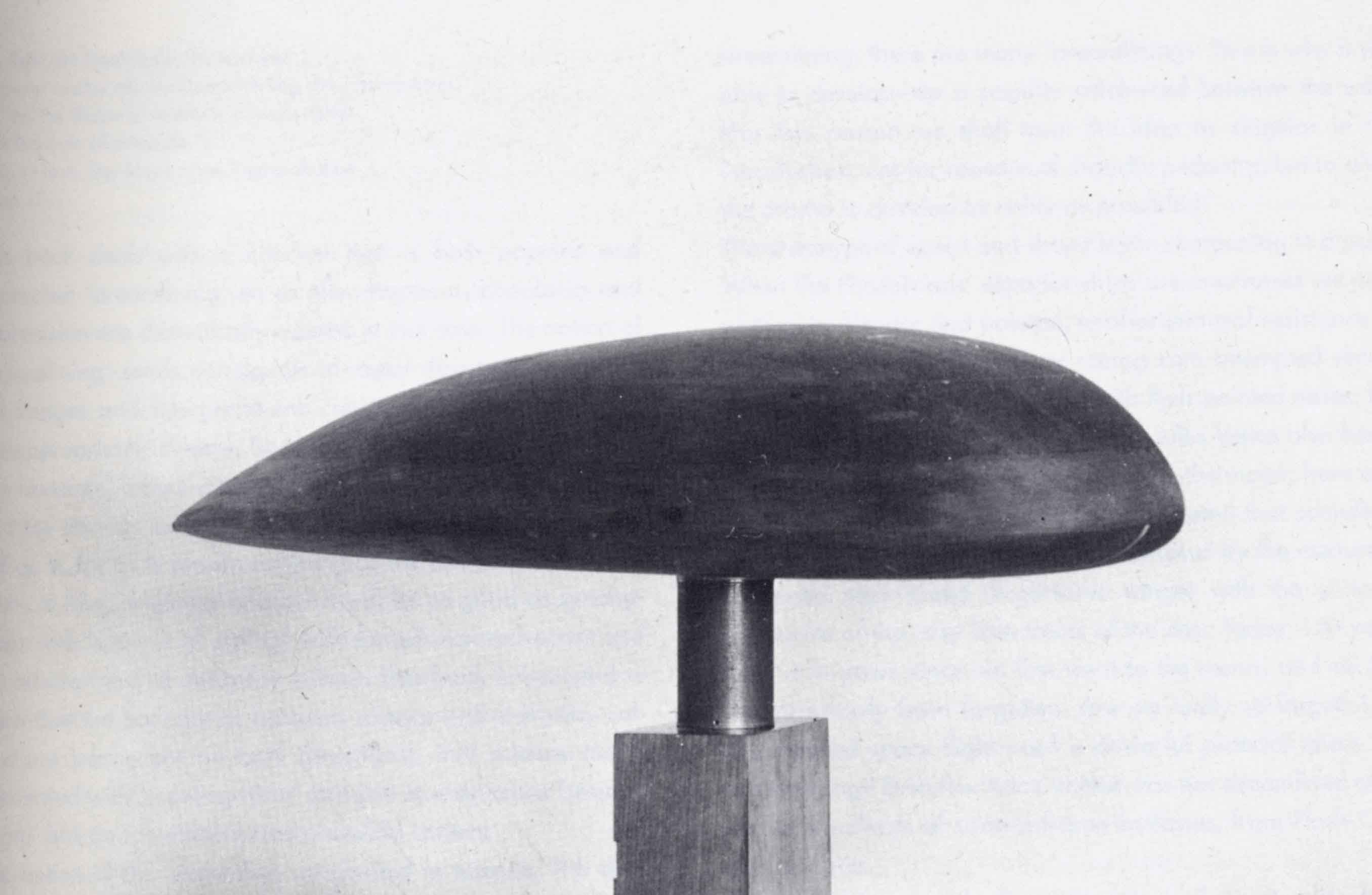
Quote:
|
One of Jaray's wind tunnel maquettes. This shape would form the basis of his car design patents.
|
__________________
George
Architect, Artist and Designer of Objects
2012 Infiniti G37X Coupe
1977 Porsche 911s Targa
1998 Chevy S-10 Pick-Up truck
1989 Scat II HP Hovercraft
You cannot sell aerodynamics in a can............
|
|
|
|
|
The Following 2 Users Say Thank You to kach22i For This Useful Post:
|
|
|
09-12-2013, 06:09 PM
|
#594 (permalink)
|
|
Master EcoModder
Join Date: Jan 2008
Location: Sanger,Texas,U.S.A.
Posts: 16,534
Thanks: 24,520
Thanked 7,438 Times in 4,818 Posts
|
jaray
Quote:
Originally Posted by kach22i
|
The infamous pumpkin seed! Cd 0.13 with wheels and on the ground.
With a bit longer body she goes to Cd 0.12.
Great 'template' material!
__________________
Photobucket album: http://s1271.photobucket.com/albums/jj622/aerohead2/
|
|
|
|
|
09-23-2013, 06:47 AM
|
#595 (permalink)
|
|
Master EcoModder
Join Date: Feb 2012
Location: Australia
Posts: 355
Thanks: 5
Thanked 76 Times in 50 Posts
|
Thanks for posting that info, I made up my own spreadsheet and charts at bottom:
Quote:
Originally Posted by 3-Wheeler

After digging around for a mathematical solution to the posted equation by Mathematica, I came across a description of what is meant by "sin^m" listed above.
The math form below shows another way of handing the "sin^m", which is not solvable by normal means.

So now we had a way of properly solving the shape of a Tear Drop, and an excerpt is shown below. Here are the equations for X and Y:
X=COS(A10)
Y=SIN(A10)*SIN((A10/2)^$F$8)/$C$7
Where:
Increment = 0.1 (number of desired steps in shape)
A10 = cell A10
$C$7 = 1.925 (constant) used to create a shape with a 2.5:1 length/width ratio
$F$8 = M (constant)
And here is what the spreadsheet data looks like....

To solve for a shape where Y is positive, vary T from 0 to PI. To solve for a shape where Y is negative, vary T from PI to 2PI. In this case I am only interested in solving for Y in the positive state, so T is varied from 0 to PI.
Here is the original graph presented by SGT.
I'm not sure about the Y-axis units for this graph, as they do not give output of 2.5:1 for length/width.

The graph below however does indeed maintain AeroHead's 2.5:1 length/width ratio however. We have "two units" in the X-axis (-1 to +1) and one-half of the 0.8 units of width (0.4 units) shown. 2.0/0.8 = 2.5:1

SGT, thanks for posting your original graph of this shape, as it gave me the incentive to dig deeper for those who are math challenged, like myself.
Hope this helps, Jim. |
I did the chart with mirror image to see how uniform shape is, I think it looks pretty good, be good if someone can overlay the templates to compare, don't have the knack of doing overlays.


The shape is more aggressive at the start, bit like new template, then it tapers back and angle begins to reduce somewhere around 75% and ultimately goes back to 0 at 100%.
Although this is not in line with template theory, I actually thinks it makes more sense.
If an object is moving through free air and ultimate aero principles is to allow air to fall back in behind it, then it is better to have a trailing edge with minimum angle rather than one where two airstreams are meeting at 44°, ie 22 above and 22 below, either way it doesn't matter much as most will not go beyond 80% and you can see at 98% it is still at 13°. |
|
|
|
|
The Following 2 Users Say Thank You to Tesla For This Useful Post:
|
|
|
09-23-2013, 01:00 PM
|
#596 (permalink)
|
|
Not Doug
Join Date: Jun 2012
Location: Show Low, AZ
Posts: 12,314
Thanks: 7,327
Thanked 2,246 Times in 1,733 Posts
|
|
|
|
|
|
The Following 2 Users Say Thank You to Xist For This Useful Post:
|
|
|
09-23-2013, 01:49 PM
|
#597 (permalink)
|
|
Master EcoModder
Join Date: Dec 2008
Location: Southern WI
Posts: 829
Thanks: 101
Thanked 563 Times in 191 Posts
|
Quote:
Originally Posted by Tesla
Thanks for posting that info, I made up my own spreadsheet and charts at bottom: ......
|
What value of "M" did you use for the calculated shape?
It looks like the value was different than 1.0, since there is a "tail" present.
I suspect that if the tail was not there, the shape would match the "template" a little better.
Jim. |
|
|
|
|
09-23-2013, 04:52 PM
|
#598 (permalink)
|
|
Master EcoModder
Join Date: Feb 2012
Location: Australia
Posts: 355
Thanks: 5
Thanked 76 Times in 50 Posts
|
Xist, thanks for overlay, the curve is definately more agressive then original template, I was thinking it is much closer to the new version below with the steeper angles at the start.
3 Wheeler, I manipulated both constants until I got exactly 2.5 aspect ratio and 1.78 tail ratio, to get this M = 1.4754408 and l/w = 1.9130000020752, the original values for the constants of 1 & 1.925 gave a tail ratio of 1.67 and yes is still increasing angle at end of tail, but does not fit template that well either.
I like this equation and will fiddle a bit more and try out different combinations, I can get a closer version with less kink in tail, but the aspect ratio is around 2.54 with a 1.78 tail ratio, so there are plenty of options to choose, later tonight I will try put up a version where the tail reaches max curvature without changing direction.
Quote:
Originally Posted by betasniper
Yeah, It was about a 15° angle at the end for that one because the thickness was only 35% (Eppler 863). I posted that airfoil because that was the largest symmetric airfoil I found in that database. There is a very slightly unsymmetric airfoil which is a 38.8% thickness (Eppler 864), but even that one only goes to an 18° angle.
I put the AST-2 Template into Solidworks and tried as best as I could to make a simple spline fit the Template but These are the angles I got:

Largest deviation (angle wise) was the very first angle with a 1.3° discrepancy. Everything else is within .4°. The grey dimensions are driven and Σ's are equations. Only the black Numbers without Σ can be altered (The 500 and the 23°). The blue lines above the spline represent the curvature. Bigger lines means more curve, Smaller lines means flatter.
Edit: Even though the angle discrepancy is large, the spline I drew was slightly slower curve than the template. Very slight.
Code:
Percentage | 0% | 10% | 20% | 30% | 40% | 50% | 60% | 70% | 80% | 90% | 100% |
X | 0 | 172 | 344 | 516 | 688 | 860 | 1032 | 1204 | 1376 | 1548 | 1720 |
Y | 500.00 | 488.92 | 461.69 | 423.61 | 377.54 | 325.23 | 267.81 | 206.09 | 140.62 | 71.81 | 0 |
Angle | 0° | 6.8° | 10.9° | 13.9° | 16.0° | 17.7° | 19.1° | 20.3° | 21.3° | 22.2° | 23.0° |
|
|
|
|
|
|
The Following 4 Users Say Thank You to Tesla For This Useful Post:
|
|
|
09-30-2013, 05:46 PM
|
#599 (permalink)
|
|
Master EcoModder
Join Date: Jan 2008
Location: Sanger,Texas,U.S.A.
Posts: 16,534
Thanks: 24,520
Thanked 7,438 Times in 4,818 Posts
|
overlay
Quote:
Originally Posted by Tesla
Xist, thanks for overlay, the curve is definately more agressive then original template, I was thinking it is much closer to the new version below with the steeper angles at the start.
3 Wheeler, I manipulated both constants until I got exactly 2.5 aspect ratio and 1.78 tail ratio, to get this M = 1.4754408 and l/w = 1.9130000020752, the original values for the constants of 1 & 1.925 gave a tail ratio of 1.67 and yes is still increasing angle at end of tail, but does not fit template that well either.
I like this equation and will fiddle a bit more and try out different combinations, I can get a closer version with less kink in tail, but the aspect ratio is around 2.54 with a 1.78 tail ratio, so there are plenty of options to choose, later tonight I will try put up a version where the tail reaches max curvature without changing direction.
|
It's very close.
The emphasis with the 'Template' is the aft-body contour,ignoring the front for the most part.
Once past the max. camber position,the boundary layer has no reason to remain attached unless it sees a very stringent deceleration/ pressure-rise
gradient.
As long as the contours are 'close' to the 2.5:1 streamline half-body we should be pretty safe.But it's the back we're most interested in.
Nice work! 
__________________
Photobucket album: http://s1271.photobucket.com/albums/jj622/aerohead2/
|
|
|
|
|
The Following User Says Thank You to aerohead For This Useful Post:
|
|
|
10-01-2013, 08:20 AM
|
#600 (permalink)
|
|
Master EcoModder
Join Date: Feb 2012
Location: Australia
Posts: 355
Thanks: 5
Thanked 76 Times in 50 Posts
|
Thanks for that, I still need to play with this equation a bit more.
I've been reading a variety of things from Semi-Truck aero through to Belbouth design for engine air intakes, but one thing that struck a chord was rocket nozzle theory.
A perfect rocket nozzle will have maximum efficiency when gass departing is at the same pressure as the surrounding atmosphere, if it is higher it is wasted energy, when it is lower pressure it creates drag.
From this, in an abstract way I started to look at template theory as an inverted rocket nozzle, the ultimate goal is to leave the air behind the vehicle completely stationary, as if the vehicle had never been there.
|
|
|
|
|