06-29-2009, 10:35 PM
|
#1861 (permalink)
|
|
EcoModding Apprentice
Join Date: May 2009
Location: Orrville, Ohio
Posts: 108
Thanks: 9
Thanked 2 Times in 2 Posts
|
Hey, Paul. sounds like you have some full days ahead. From what I have seen, I am sure you will come up wih something good.  Take care, Watt 
|
|
|

|
 Today Today
|
|
|
|
 Other popular topics in this forum...
|
|
|
|
|
06-29-2009, 10:57 PM
|
#1862 (permalink)
|
|
EV test pilot
Join Date: Jan 2008
Location: Oconomowoc, WI, USA
Posts: 4,435
Thanks: 17
Thanked 663 Times in 388 Posts
|
If you want to do something REALLY cool for end caps, make them out of neon green lexan and put a small UV blacklight (fluorescent type) inside.
Otherwise, clear plexi with a few LEDs going into the edge would be cool too!
|
|
|
|
|
06-29-2009, 11:28 PM
|
#1863 (permalink)
|
|
EcoModding Apprentice
Join Date: May 2009
Location: Orrville, Ohio
Posts: 108
Thanks: 9
Thanked 2 Times in 2 Posts
|
 Controller temp tests
I know this is slightly off topic, but I would like to see how the Open Revolt that is going to arizona does. Was getting ready to turn in, and the weather channel was on tv. It was 108 Degrees there today(according to them).WHEW  Too hot for me! Have a good one. Watt |
|
|
|
|
06-30-2009, 01:05 AM
|
#1864 (permalink)
|
|
Joe
Join Date: Feb 2009
Location: phx
Posts: 260
Thanks: 0
Thanked 48 Times in 38 Posts
|
Quote:
Originally Posted by watt-a-mezz

I know this is slightly off topic, but I would like to see how the Open Revolt that is going to arizona does. Was getting ready to turn in, and the weather channel was on tv. It was 108 Degrees there today(according to them).WHEW Too hot for me! Have a good one. Watt |
I do too! My plan is to either start a testing thread or add info/updates in the wiki. or both! Its just starting to get hot, so perfect timing for some "hot day" testing. |
|
|
|
|
06-30-2009, 03:30 PM
|
#1865 (permalink)
|
|
ReVolt Enthusiast
Join Date: Jun 2009
Location: Michigan, USA
Posts: 239
Thanks: 97
Thanked 47 Times in 40 Posts
|
Good stuff !!!
Hi Paul,
I am new to this group, the past few days I have finished reading all the thread pages for the Revolt EV Motor Controller. What this group has accomplished is very impressive !!! I would be willing to help on this open source ReVolt project. I have experience in PCB design and electro-mechanical packaging.
Reading through the threads I understand that the Revolt has been designed as a scalable modular EV DC motor controller. Back on some of the earlier threads, there was talk of some different power versions of the Revolt. I believe the power module that you are working on now is rated around 144V @ 500A. What needs to be done to increase the current rating on the ReVolt unit ? Is it just adding more mosfet/diode/capacitor pairs and increasing the current limit range ? Would that require a software change too ?
What is the power rating for a mosfet/diode pair on the present power module ? The irfp4668 mosfet is rated at 130A @ 200V, and the stth6002 diode pair at 60A @ 200V. You said in one of the threads that they were rated around 50 amps per mosfet/diode pair, is this still true ? I am interested in the design of a modular chassis for the ReVolt that would allow you to increase the current rating by adding power module PCBs (1-mosfet, 1-diode, 2-power capacitors ,1-gate resistor). They would just bolt to the buss bars, and the heatsink. You could repair or upgrade a bad power mosfet by swapping out a power module PCB, not the whole power PCB like you are using now. Using a standard buss bar chassis, the ReVolt could be assembled as a 500A, 750A, 1000A, etc
. controller by just adding additional individual power module PCBs.
Thats my 2 cents.
PS. Can someone add the latest schematic rev2C to the wiki ??? |
|
|
|
|
06-30-2009, 05:10 PM
|
#1866 (permalink)
|
|
Losing the MISinformation
Join Date: Oct 2008
Location: Southern Missouri
Posts: 393
Thanks: 15
Thanked 3 Times in 3 Posts
|
Hey, Y'all, don't forget that JOB ONE here is to make an AFFORDABLE controller...
Otherwise, I ain't gonna to be able to buy back the two mosfets I sponsored! 
__________________

The brake pedal is my enemy. The brake pedal is my enemy. The brake pedal...
|
|
|
|
|
06-30-2009, 08:43 PM
|
#1867 (permalink)
|
|
PaulH
Join Date: Feb 2008
Location: Maricopa, AZ (sort of. Actually outside of town)
Posts: 3,832
Thanks: 1,362
Thanked 1,202 Times in 765 Posts
|
Quote:
Originally Posted by sawickm
What needs to be done to increase the current rating on the ReVolt unit ? Is it just adding more mosfet/diode/capacitor pairs and increasing the current limit range ? Would that require a software change too ?
|
If we used 2 mosfet drivers instead of just 1, things would be much more scalable. I think your idea would work really well. On the next version, we should really try to use 2 drivers. Ian of Zeva is using 4 right now, for 12 mosfets. It's working really well, and helps to keep things cooler, since he can then afford to use really really small gate resistors. It would require VERY minor software changes.
Quote:
Originally Posted by sawickm
What is the power rating for a mosfet/diode pair on the present power module ? The irfp4668 mosfet is rated at 130A @ 200V, and the stth6002 diode pair at 60A @ 200V. You said in one of the threads that they were rated around 50 amps per mosfet/diode pair, is this still true ?
|
50 amps per pair seems to be pretty safe. I would really like to change it to synchronous rectification, so we can use a mosfet/mosfet pair instead. The diode is really the weak link.
Quote:
Originally Posted by sawickm
I am interested in the design of a modular chassis for the ReVolt that would allow you to increase the current rating by adding power module PCBs (1-mosfet, 1-diode, 2-power capacitors ,1-gate resistor). They would just bolt to the buss bars, and the heatsink. You could repair or upgrade a bad power mosfet by swapping out a power module PCB, not the whole power PCB like you are using now. Using a standard buss bar chassis, the ReVolt could be assembled as a 500A, 750A, 1000A, etc
. controller by just adding additional individual power module PCBs.
|
This sounds like a very good idea. I'm sure it could be made to work. There would only need to be minor changes, like where to put the bolts. If we had 1 bolt per mosfet/diode pair, instead of only like 4 or 5 (or whatever) altogether. |
|
|
|
|
06-30-2009, 08:54 PM
|
#1868 (permalink)
|
|
EcoModding Lurker
Join Date: May 2009
Location: Bremerton, Wa
Posts: 41
Thanks: 0
Thanked 0 Times in 0 Posts
|
Still awesome! I can't wait for the synchronous rectification version, especially with MORE POWER, and a fully modular approach to that would be just insane...but I've seen a great deal of other things get going and take a lot longer just to get somewhere...keep up the great work! I'm still saving for my EV >.< But I want to use a ReVolt controller, mostly because it's awesome.
|
|
|
|
|
07-01-2009, 01:07 AM
|
#1869 (permalink)
|
|
PaulH
Join Date: Feb 2008
Location: Maricopa, AZ (sort of. Actually outside of town)
Posts: 3,832
Thanks: 1,362
Thanked 1,202 Times in 765 Posts
|
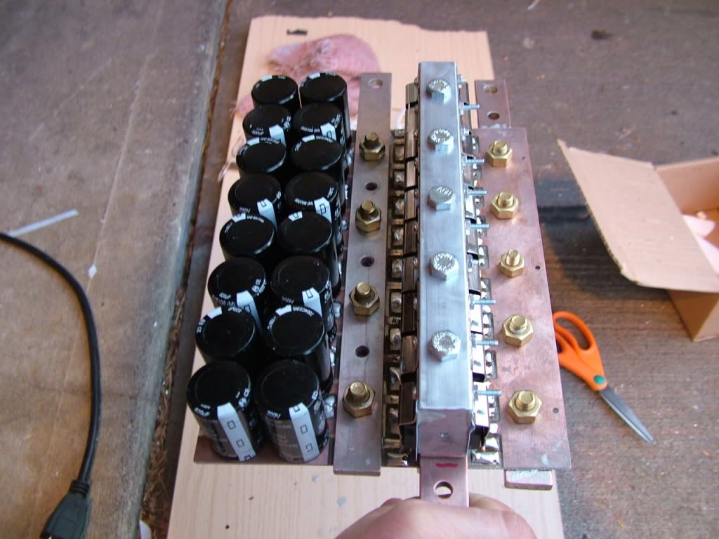
Ben's is getting close to being done (sort of close). That 3/8" aluminum plate came today, so I need to cut it and drill the holes. Also, I need to widen the bottom of the holes of the plate for Joe so little screws can be put through the bottom to hold the enclosure in place. Here's a picture of Ben's. I couldn't find the camera for a long time! makes me mad!
 |
|
|
|
|
07-01-2009, 04:33 AM
|
#1870 (permalink)
|
|
EcoModding Apprentice
Join Date: May 2009
Location: Australia
Posts: 109
Thanks: 0
Thanked 2 Times in 2 Posts
|
Paul (and others),
Is there a particular reason that a diode pair per MOSFET is used, rather than one higher rated device? That is a single device to protect the whole array of MOSFETs
Last edited by squiggles; 07-01-2009 at 08:35 AM..
Reason: clarity
|
|
|
|
|