Go Back   EcoModder Forum > EcoModding > Aerodynamics
Register Now
 Register Now
 

Reply  Post New Thread
 
Submit Tools LinkBack Thread Tools
Old 02-12-2013, 12:44 PM   #41 (permalink)
Aero Wannabe
 
COcyclist's Avatar
 
Join Date: Dec 2007
Location: NW Colo
Posts: 738

TDi - '04 VW Golf
TEAM VW AUDI Group
90 day: 53.2 mpg (US)
Thanks: 705
Thanked 218 Times in 169 Posts
Quote:
Originally Posted by christofoo View Post
In the interest of not loosing our stuff and ruining a family trip, I put some thought into the most prominent forces the frame has to withstand, i.e. the bumpy road scenario.
Are you going to add a reinforcing triangle of steel as you show in this drawing just to the right of where you have the curving arrow showing 800 ft/lbs of force? I see this as a high stress area. A sudden bump will try to separate your weld here. I believe you WILL need to over-engineer this joint.

Your pivot point could be anchored to the edge of the trunk lip with some straps. Looks great! Can't wait!

__________________
60 mpg hwy highest, 50+mpg lifetime
TDi=fast frugal fun
https://ecomodder.com/forum/showthre...tml#post621801


Quote:
Originally Posted by freebeard View Post
The power needed to push an object through a fluid increases as the cube of the velocity. Mechanical friction increases as the square, so increasing speed requires progressively more power.

Last edited by COcyclist; 02-15-2013 at 01:33 PM..
  Reply With Quote
Alt Today
Popular topics

Other popular topics in this forum...

   
Old 02-12-2013, 01:33 PM   #42 (permalink)
Master EcoModder
 
christofoo's Avatar
 
Join Date: Mar 2012
Location: Salt Lake City
Posts: 292

00C - '00 Toyota Corolla
90 day: 43.54 mpg (US)
Thanks: 147
Thanked 190 Times in 73 Posts
Quote:
Originally Posted by COcyclist View Post
Are you going to add a reinforcing triangle of steel as you show in this drawing just to the right of where you have the curving arrow showing 800 ft/lbs of force? I see this as a high stress area. A sudden bump will try to separate your weld here. I believe you WILL need to over-engineer this joint.

You pivot point could be anchored to the edge of the trunk lip with some straps. Looks great! Can't wait!
Exactly, those are angle-braces from 1/8" plate. I haven't put them on yet.

As a fail-safe, I'm probably going to chain the receiver to the box at the main rail and strap the top of the box to the top of the trunk. The frame should never fail though.

The strap could be preloaded to take some stress off the joints, in practice it'll have some tension; but I view it primarily as a fail-safe.
  Reply With Quote
The Following User Says Thank You to christofoo For This Useful Post:
aerohead (02-16-2013)
Old 02-14-2013, 07:14 PM   #43 (permalink)
AeroGuy
 
eco_generator's Avatar
 
Join Date: Sep 2008
Location: Ohio
Posts: 224

Outback 14 - '14 Subaru Outback Limited
90 day: 23.1 mpg (US)
Thanks: 73
Thanked 32 Times in 28 Posts
I like this thinking through problems before you have them.

My wife would disagree, lol.
  Reply With Quote
Old 03-14-2013, 04:20 PM   #44 (permalink)
Master EcoModder
 
christofoo's Avatar
 
Join Date: Mar 2012
Location: Salt Lake City
Posts: 292

00C - '00 Toyota Corolla
90 day: 43.54 mpg (US)
Thanks: 147
Thanked 190 Times in 73 Posts
Quote:
Originally Posted by eco_generator View Post
I like this thinking through problems before you have them.

My wife would disagree, lol.
I know what you mean on both fronts. I really want to get it right the first time. But sometimes it seems more productive to just dive in and take a swag at it.
  Reply With Quote
Old 03-14-2013, 05:37 PM   #45 (permalink)
Master EcoModder
 
christofoo's Avatar
 
Join Date: Mar 2012
Location: Salt Lake City
Posts: 292

00C - '00 Toyota Corolla
90 day: 43.54 mpg (US)
Thanks: 147
Thanked 190 Times in 73 Posts
More planning updates; skin/rib/lid plan

Prep for the sheet metal skin (phase 2) required a lot of head-scratching, but I think I'm about ready to fab now (or whenever the illness around my house clears up).

First off, 3dcadbrowser's human reviewer rejected my upload, which came as a surprise. I'll probably try again... later... (because I really really want a Prius CAD model, if not the Civic model.)

So I clamped some strips together on top of the frame in the real world, eyeballed the tail profile, and then took the dimensions from the strips. This is a pretty good way of doing it anyhow.


I had the box height exactly right, but it turns out the width I got from my diagrams was about 5 inches short. I adjusted my design accordingly, but I'm not going to change the steel floor frame now - it won't look quite right, but a typical load isn't going to unduly stress the edges.

Most of the head-scratching went into deciding where to place the ribs and how to constrain and assemble everything and whether I needed a buck. Here's what I came up with:
  • I bought a 4'x12' .032 thick Aluminum sheet from a local supplier for only $56. So far that's the only thing that's cost less than I expected. The sheet was pretty easy to roll up and fit in my Corolla's backseat for the trip home. At $1.17 per sqft, I have a feeling this will become my ecomodding material of choice for a variety of mods.
  • The lid will be fiberglass over foam (like a surfboard or like 3wheeler's Insight tail).
  • The lid hinge is in the back and the lid is cut low in the front so that large items can be removed from the trunk while the box is on the hitch. (BTW it turns out the pin for the frame hinge is not easy to remove and replace; alignment is challenging. So that isn't the right method to get large items in and out of the trunk.)
  • The skin will be in 2 pieces; front and back. The back piece starts on bottom and folds up over the sides and back. The front piece has 2 compound corners to shrink (which are not shown in the CAD; Solidworks doesn't like to make compound sheet metal). Actually in order to fit the front piece onto the 4'x12' sheet I have to cut it out in two halves and rivet it together. Details, details.
  • First step is to rivet the rear skin onto the floor frame. The very tail end shape is constrained with a thin plywood form. (It goes on the inside of the skin; I didn't do that exploded view quite right.) The 0.05 thick aluminum right-angle side-ribs are attached to the skin and then the sides and back are bent up. There will be no buck; the forward section will be measured at the lip, maybe use strips to clamp securely in place, the rearward is constrained by the plywood and then the back and sides are riveted together. Then the aluminum ribs get bolted to steel brackets that weld onto the floor frame, using a welding blanket or such to protect the aluminum sheets.
  • Next step is to form the front skin, using the box itself to verify the shape. Then rivet it in place. Then add aluminum ribs and weld the front bracket on.
  • There's also a plywood lip around the curves at the top that I need for the lid to seal against.

There will be a PDF with component drawings on my website sometime later, as well as a ZIP with STEP and Solidworks CAD.

EDIT: files are ready: Index of /files
  • CAD in Solidworks format
  • CAD in STEP format
  • CAD in VRML (polygon) format
  • Drawings in PDF

The lid will be phase 3.

======================================


I also had a chance to finish the frame and put it on the car, load up the trunk with 180lbs, and drive around a bit. I did test my driveway and a dip not far away. The caster actually never struck, but at 180lbs the blue UHMW slip pad definitely bottoms out on the driveway. No surprises there.

I don't think the UHMW slip pad is going to last forever, but I'll probably put a few runs on it first, if it convinces me it is a long-term problem (and if I would be unhappy periodically replacing the slip pad) I have a backup plan for some plastic wheels that will bolt onto the front of the frame. You can see them in my CAD. I couldn't find quite the right off-the-shelf wheel, so I figure I'd cut them from plastic rod-stock and attach to bolt-on idler shafts.

Also, it would make sense to use UHMW slip pad(s) instead of the caster in the back, since ground strikes on the back end of the box have turned out to be a rather light duty application.

Last edited by christofoo; 03-16-2013 at 10:24 PM..
  Reply With Quote
The Following 2 Users Say Thank You to christofoo For This Useful Post:
aerohead (04-06-2013), turbothrush (03-14-2013)
Old 03-14-2013, 09:32 PM   #46 (permalink)
EcoModding Apprentice
 
turbothrush's Avatar
 
Join Date: Nov 2008
Location: Canada
Posts: 133

2 x wrecked vx - '92 Honda Civic Vx
Team Honda
90 day: 62 mpg (US)
Thanks: 119
Thanked 54 Times in 30 Posts
I like your idea of skid instead of a caster . In my opinion it would look better too
  Reply With Quote
Old 03-14-2013, 10:10 PM   #47 (permalink)
Master EcoModder
 
Join Date: Nov 2008
Location: Cincinnati
Posts: 323

Civic CX/HX - '97 Honda Civic CX/HX
Team Honda
90 day: 63.77 mpg (US)
Thanks: 12
Thanked 50 Times in 36 Posts
this is looking great, keep up the good work!!!
__________________
  Reply With Quote
Old 04-04-2013, 11:13 AM   #48 (permalink)
Master EcoModder
 
christofoo's Avatar
 
Join Date: Mar 2012
Location: Salt Lake City
Posts: 292

00C - '00 Toyota Corolla
90 day: 43.54 mpg (US)
Thanks: 147
Thanked 190 Times in 73 Posts
Phase 2: skin fab (howto)

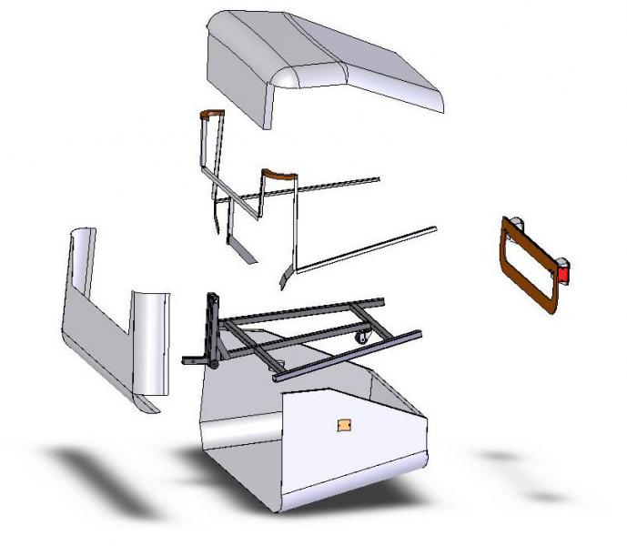
I got about 60-70% of phase 2 fab finished (the aluminum skins).

Here's some pictures to follow along (howto - style).

Not shown - I assumed the edges of my aluminum sheet were square, and transcribed (x,y) points from the drawing using a pair of tape measures from the edges. Then cut it out with aviation snips.

(I decided the plywood back piece is just a template.)
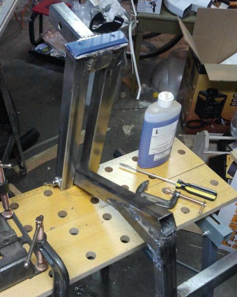
I used a 2x4 and a hammer to make this first bend. It was messy, so I tried planishing, but that was a mistake.


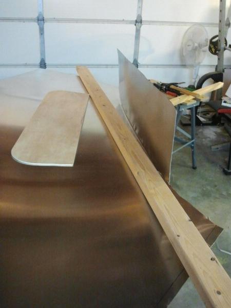
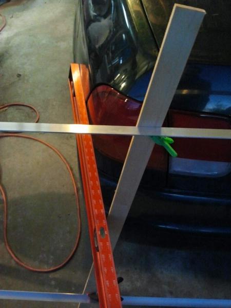
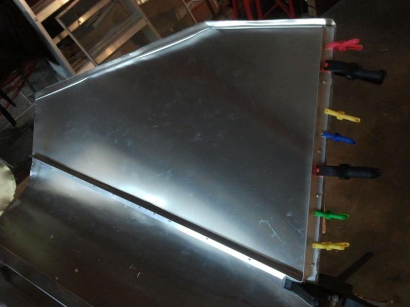
A better way to fold .032 Al is to sandwich it with 2x2's - wrist strength is fine for a .1-.25" bend radius, even progressively across a long fold. Also, this shot is after transfering the back template and snipping it out.


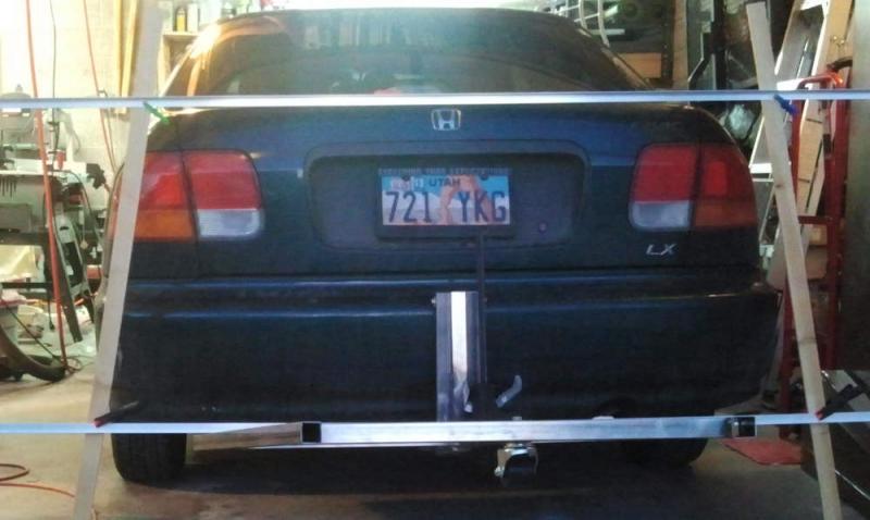
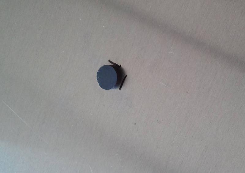
Next I want to attach the skin to the frame, so I lay it out, align it, clamp it, and use a pair of fridge magnets to find the edges of the frame.


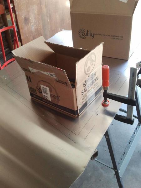
After all the edges are found, I had a trace of the frame on the bottom side of the sheet. Add some 10 lbs weights to keep the metal flat (also still clamped), and then drill all the holes for 1/8" rivets.


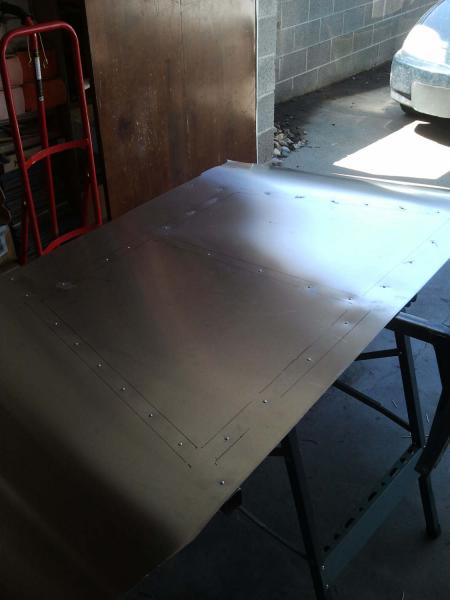
Next it's important to disassemble and debur the holes. I used a larger bit for deburring. I also applied construction adhesive. I figure if it doesn't add any strength it will at least keep it quiet. Here it is all riveted.


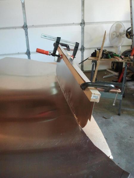
For the sides, first I put as much of the 4" radius bend into it as I can, by hand. Then sandwich and apply folds for the lip on top. Then clamp, drill, debur, glue and rivet the side-rib, made from .75x.05 aluminum right-angle.


I'm not achieving art-quality metalwork (I presume due to inexperience and/or impatience), but my wife says it looks good, and that's the crucial test here. Moreover the plan feels right - the pieces feel strong enough where they need to be. (So far.)
  Reply With Quote
The Following 2 Users Say Thank You to christofoo For This Useful Post:
aerohead (04-06-2013), bespurcell (01-16-2015)
Old 04-04-2013, 03:54 PM   #49 (permalink)
This is the year
 
Join Date: Apr 2010
Location: Columbus, OH
Posts: 36

Bug - '06 Volkswagen Beetle TDI PKG1
90 day: 37.04 mpg (US)

F-350 - '11 Ford F-350 Lariat
90 day: 16.23 mpg (US)
Thanks: 1
Thanked 2 Times in 2 Posts
Looks awesome and can't wait to see the final product. FYI welding zinc is toxic I would not attempt at all.
__________________


  Reply With Quote
The Following User Says Thank You to big shafe For This Useful Post:
christofoo (04-05-2013)
Old 04-04-2013, 06:07 PM   #50 (permalink)
Master EcoModder
 
christofoo's Avatar
 
Join Date: Mar 2012
Location: Salt Lake City
Posts: 292

00C - '00 Toyota Corolla
90 day: 43.54 mpg (US)
Thanks: 147
Thanked 190 Times in 73 Posts
Quote:
Originally Posted by big shafe View Post
Looks awesome and can't wait to see the final product. FYI welding zinc is toxic I would not attempt at all.
Thanks, and thanks for the reminder. I went back to #29 and added a warning. I knew I wasn't supposed to do it at the time, but I did it anyway, without calculating the risks. OSHA has a page describing the toxicity: Welding Health Hazards. Nothing bad happened to me - it was some months ago but I might have done it right before I left the shop to vent for the night, and IIRC I think I was mindful of keeping my face away from the smoke-stream, and on at least some of the welds I ground most of the zinc off before welding. There were also a few nights back in the cold weather I had my smog mask on - which may have had a filtering effect against zinc - but I don't remember whether that would have been one of those nights.

Here's an example of someone similarly careless who got sick: Got my first taste of Zinc poisoning... - MIG Welding Forum. So I would agree with the conventional wisdom; don't be like me, don't weld zinc plated stuff on the off chance it won't be an issue.

Of course all of the metal actually on the project is 'weldable' and not plated.

  Reply With Quote
The Following User Says Thank You to christofoo For This Useful Post:
aerohead (04-06-2013)
Reply  Post New Thread


Thread Tools


Powered by vBulletin® Version 3.8.11
Copyright ©2000 - 2024, vBulletin Solutions Inc.
Content Relevant URLs by vBSEO 3.5.2
All content copyright EcoModder.com