Go Back   EcoModder Forum > EcoModding > Fossil Fuel Free
Register Now
 Register Now
 

Reply  Post New Thread
 
Submit Tools LinkBack Thread Tools
Old 10-23-2015, 08:43 PM   #2231 (permalink)
Permanent Apprentice
 
Join Date: Jul 2010
Location: norcal oosae
Posts: 523
Thanks: 351
Thanked 314 Times in 215 Posts
So here are a few more views of the compact inverter.

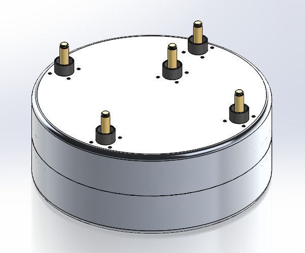
This design is very compact and pretty light. The dry weight at this point is 6.35kg. Its volume is 6.1 L, not including the output pins. Its main case is 104mm tall and 272mm in diameter. These specs are a bit smaller/lighter than the OE Toyota specs. Of course the power/weight numbers depend heavily on how many switches are used and how hard they are driven.

The main foundation is like the previous pic I posted. I've been working out issues like sealing out the coolant, fastening stuff, and packaging things as small as reasonable.

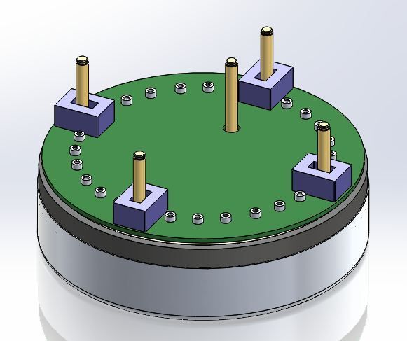
The current sensor problem worked out pretty well. You can use the standard LEM current sensors with a couple small mods: - Cut the bolt flange off and cut off the little plastic guide around the connection pins. Note also that everything is on one controller board. There is no need for any extra connections. Temperature sensing would be easy and accurate by just putting a thermistor on the bus pan.

The input/output pins are 10mm radlock pins. These are very reliable, high current density parts - the 10mm pin can handle 300A. I've also used the 3.6mm radsock connector for the gate connection. Again, these are very high reliability parts with a helical contact to the pin. They can handle WAY more current than is necessary to drive the switch. Another option would be to directly solder the gate legs to the circuit board. Of course that would make disassembly nearly impossible.

I've shown in the drawings a design that uses all the parts that could possibly fit. Of course they can be left off in reality - for example, there are four current sensors shown - one for the input booster and one for each phase.

It would also be easy to skip the boost converter part. The input high side would just connect directly to the lower bus plate. It would give room for more switches, so the inverter could be capable of a higher output.

So, with a boost converter, it's possibe to fit 6 switches per phase - or 3 high, 3 low.
Without a boost converter, it's possible to fit 8 switches per phase. At this point, it would be limited to the output pin capability of 300A. Of course the larger pin could be used, but at this point we're looking at about 195kW with a 650V input.

I'm still working out the cooling details, but generally it's using a cooling oil that circulates around the capacitor and between the plates. The switch legs are immersed in flowing coolant, as are the output bus bars. Hot spots on the legs, switches etc. should not be an issue.

Controller with the top cover, removed and the low side plate transparent:


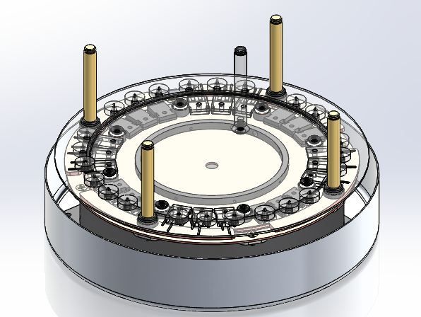
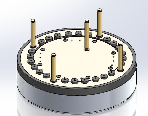
Here is the insulator/seal shown with the low side plate visible.


Here is the circuit board: Note the modded current sensors and the connectors for the gate pins:


Here is a nearly complete inverter. It still needs connectors for the controller and coolant connections.


- E*clipse

  Reply With Quote
The Following 2 Users Say Thank You to e*clipse For This Useful Post:
MPaulHolmes (10-23-2015), thingstodo (10-23-2015)
Alt Today
Popular topics

Other popular topics in this forum...

   
Old 10-23-2015, 08:52 PM   #2232 (permalink)
Master EcoModder
 
Join Date: Sep 2010
Location: Saskatoon, canada
Posts: 1,488

Ford Prefect - '18 Ford F150 XLT XTR

Tess - '22 Tesla Y LR
Thanks: 749
Thanked 565 Times in 447 Posts
Quote:
Originally Posted by MPaulHolmes View Post
I think I"m going to have 2 separate power boards. One with electrolytic caps, and one with dc link film caps. You can fit 12 of 60uF film caps, for a total ripple rating of about 200amp. But the cost is about $160. You can also do 15 of 470uF 400v electrolytic caps that have similar characteristics to the ones I use in the 500amp DC controller (so I know it would be good enough). That would also make the DC bus change much more slowly from the boosting and bucking (millisec instead of microsec) so you wouldn't have to be quite as vigilant in the software. And then you can also do it for $59. So, then the cost of parts would be $290 (in quantity 1) or so. Well, you would need an extra current sensor, dang it. I can only fit 2 on the power board.The 3000hour rating isn't such a big deal. That's like 1 hour of driving daily for 9 years.
Are you ready to build these for testing?

My wife is in Mesa for the next 3 weeks and could transport a couple of them home for torture testing It would save some shipping costs!

With 8s2p of the Leaf tins I can configure 64V nominal at 120A (1C) or 360A (3C) for a minute or so. Just a suggestion
  Reply With Quote
The Following User Says Thank You to thingstodo For This Useful Post:
MPaulHolmes (10-23-2015)
Old 10-23-2015, 10:15 PM   #2233 (permalink)
Permanent Apprentice
 
Join Date: Jul 2010
Location: norcal oosae
Posts: 523
Thanks: 351
Thanked 314 Times in 215 Posts
Quote:
Originally Posted by MPaulHolmes View Post
I think I"m going to have 2 separate power boards. One with electrolytic caps, and one with dc link film caps. You can fit 12 of 60uF film caps, for a total ripple rating of about 200amp. But the cost is about $160. You can also do 15 of 470uF 400v electrolytic caps that have similar characteristics to the ones I use in the 500amp DC controller (so I know it would be good enough). That would also make the DC bus change much more slowly from the boosting and bucking (millisec instead of microsec) so you wouldn't have to be quite as vigilant in the software. And then you can also do it for $59. So, then the cost of parts would be $290 (in quantity 1) or so. Well, you would need an extra current sensor, dang it. I can only fit 2 on the power board.The 3000hour rating isn't such a big deal. That's like 1 hour of driving daily for 9 years.
- I'm wondering about the possibilities of integrating it with the circular design.
- Those ring caps can take huge ripple currents IE the 700V/1000uF cap can handle 300Arms @ 85C. Would this be adequate for a shared inverter/booster?
- What is **rougly** the board area requirement for the booster? I'm guessing the inverter area would be similar to the rev2 version, right?
- integrating boost inductor would be an issue. How about externally, with some plugs or maybe vertically, underneath the bus capacitor?

- E*clipse
  Reply With Quote
Old 10-23-2015, 10:38 PM   #2234 (permalink)
Master EcoModder
 
Join Date: Sep 2010
Location: Saskatoon, canada
Posts: 1,488

Ford Prefect - '18 Ford F150 XLT XTR

Tess - '22 Tesla Y LR
Thanks: 749
Thanked 565 Times in 447 Posts
Quote:
Originally Posted by e*clipse View Post
- integrating boost inductor would be an issue. How about externally, with some plugs or maybe vertically, underneath the bus capacitor?
How are you planning to mount your controller?

Why do I ask? If it is very close to the motor, mounting the inductor between the motor and the controller allows using the motor as a heat sink for both the controller and the inductor.

Hmm. The controller likely wants to be MUCH cooler than the motor needs to be. Perhaps the controller can be the heat sink? But it makes more sense to have the motor tightly coupled to the motor casing ... and the inductor kinda pasted onto the side of the motor casing?

As usual, this would likely cause some noise to interfere with the operation of the controller.
Attached Thumbnails
Click image for larger version

Name:	Inductor.jpg
Views:	60
Size:	86.1 KB
ID:	18938  
  Reply With Quote
The Following 2 Users Say Thank You to thingstodo For This Useful Post:
e*clipse (10-23-2015), MPaulHolmes (10-23-2015)
Old 10-23-2015, 11:54 PM   #2235 (permalink)
PaulH
 
MPaulHolmes's Avatar
 
Join Date: Feb 2008
Location: Maricopa, AZ (sort of. Actually outside of town)
Posts: 3,832

Michael's Electric Beetle - '71 Volkswagen Superbeetle 500000
Thanks: 1,368
Thanked 1,202 Times in 765 Posts
The 3 boards I'm doing are meant for ghetto cheap "put it together yourself in the jungle with only a hand drill". The schematic would basically be the same though. Just stick the components in different spots on a circular driver board and control board.

EDIT: They don't yet exist in real life. JUst on the the computer, so I can't send it up to you, thingstodo. I wish it was done!
__________________
kits and boards

Last edited by MPaulHolmes; 10-24-2015 at 12:17 AM..
  Reply With Quote
The Following 2 Users Say Thank You to MPaulHolmes For This Useful Post:
e*clipse (10-24-2015), thingstodo (10-24-2015)
Old 10-24-2015, 02:40 AM   #2236 (permalink)
Permanent Apprentice
 
Join Date: Jul 2010
Location: norcal oosae
Posts: 523
Thanks: 351
Thanked 314 Times in 215 Posts
Quote:
Originally Posted by thingstodo View Post
How are you planning to mount your controller?

Why do I ask? If it is very close to the motor, mounting the inductor between the motor and the controller allows using the motor as a heat sink for both the controller and the inductor.

Hmm. The controller likely wants to be MUCH cooler than the motor needs to be. Perhaps the controller can be the heat sink? But it makes more sense to have the motor tightly coupled to the motor casing ... and the inductor kinda pasted onto the side of the motor casing?

As usual, this would likely cause some noise to interfere with the operation of the controller.
I'm planning to mount the controller pretty close to the motor. Basically right next to the motor, but in a less harsh environment.

I'm planning to use a separate cooling system for the motors and controllers; they could probably use the same system, as I'm probably going to use ATF as the fluid in both. I'm
not sure about that yet; it could save some hardware.

Like you say, the controllers would like cooler fluid than the motors. Also the motor's oil is shared by the gearbox - it won't necessarily be clean.

- E*clipse
  Reply With Quote
Old 10-24-2015, 02:57 AM   #2237 (permalink)
Permanent Apprentice
 
Join Date: Jul 2010
Location: norcal oosae
Posts: 523
Thanks: 351
Thanked 314 Times in 215 Posts
Quote:
Originally Posted by MPaulHolmes View Post
The 3 boards I'm doing are meant for ghetto cheap "put it together yourself in the jungle with only a hand drill". The schematic would basically be the same though. Just stick the components in different spots on a circular driver board and control board.

EDIT: They don't yet exist in real life. JUst on the the computer, so I can't send it up to you, thingstodo. I wish it was done!
Yea, this certainly doens't meet those specs - LOL! The primary goal in this case is something light and small, since I will need 4 of them.

So - some quickee measurements - The new designs circuit board is about 265mm in diameter. That works out to about 85 square inches, minus the current sensors, etc.

The rev 2 revolt board is about 40 sq. in. So, there should be enough room for a boost stage!

- E*clipse
  Reply With Quote
The Following User Says Thank You to e*clipse For This Useful Post:
MPaulHolmes (10-24-2015)
Old 10-24-2015, 12:09 PM   #2238 (permalink)
PaulH
 
MPaulHolmes's Avatar
 
Join Date: Feb 2008
Location: Maricopa, AZ (sort of. Actually outside of town)
Posts: 3,832

Michael's Electric Beetle - '71 Volkswagen Superbeetle 500000
Thanks: 1,368
Thanked 1,202 Times in 765 Posts
Here's a graph of the magnitude of <Vd,Vq> in blue, and the rotor flux speed in reddish-orange. I let it spin up pretty fast, and then pushed on the flywheel with a plastic cup, which melted the cup, but notice how nicely it tracked it! There was no filtering at all on the magnitude of <Vd,Vq>. But my "magnitude" algorithm didn't involve a square root, so I need to double check that it is accurate over the full range:


So, you really ONLY have to pay attention to the RPM for knowing when you need to boost. Load makes absolutely no difference. By the way, you could probably get a loosy goosy sensorless working with ONLY using the magnitude of <Vd,Vq>. At least good enough for use with a 4 or 6 count hall effect thing.
__________________
kits and boards
  Reply With Quote
The Following 2 Users Say Thank You to MPaulHolmes For This Useful Post:
e*clipse (10-24-2015), thingstodo (10-24-2015)
Old 10-24-2015, 05:03 PM   #2239 (permalink)
Permanent Apprentice
 
Join Date: Jul 2010
Location: norcal oosae
Posts: 523
Thanks: 351
Thanked 314 Times in 215 Posts
Quote:
Originally Posted by MPaulHolmes View Post
Here's a graph of the magnitude of <Vd,Vq> in blue, and the rotor flux speed in reddish-orange. I let it spin up pretty fast, and then pushed on the flywheel with a plastic cup, which melted the cup, but notice how nicely it tracked it!

So, you really ONLY have to pay attention to the RPM for knowing when you need to boost. Load makes absolutely no difference. By the way, you could probably get a loosy goosy sensorless working with ONLY using the magnitude of <Vd,Vq>. At least good enough for use with a 4 or 6 count hall effect thing.
That's a really cool test - I was wondering about that as I looked @ the ORNL Prius BEMF test - it's perfectly linear.

- E*clipse
  Reply With Quote
Old 10-24-2015, 06:55 PM   #2240 (permalink)
Permanent Apprentice
 
Join Date: Jul 2010
Location: norcal oosae
Posts: 523
Thanks: 351
Thanked 314 Times in 215 Posts
Paul - you mentioned using a combination of the 4011 and 2010 for the inverter functions and boost functions.

I know you're not a fan of the surface mount stuff, but have you looked into the 5015's or 6015's?

According to the spec sheets, they have motor control PWM channels. Have you looked at whether it's possible to run 6 channels for standard 3 phase and **completely independantly** 2 channels for the boost control?

Or would it be at least possible to run 6 channels as 3 phase with 2 channels running a different PWM, as necessary? Perhaps sharing the same switching frequency...

Any idea of how independantly these channels can be operated?

Thanks a bunch,

E*clipse

  Reply With Quote
Reply  Post New Thread


Similar Threads
Thread Thread Starter Forum Replies Last Post
Paul & Sabrina's cheap DIY 144v motor controller MPaulHolmes Open ReVolt: open source DC motor controller 7381 08-02-2023 10:55 PM
Paul & Sabrina's Cheap EV Conversion MPaulHolmes Fossil Fuel Free 542 11-12-2016 09:09 PM
Contest! Name Paul & Sabrina's controller MetroMPG Forum News & Feedback 120 10-22-2011 01:59 PM


Powered by vBulletin® Version 3.8.11
Copyright ©2000 - 2024, vBulletin Solutions Inc.
Content Relevant URLs by vBSEO 3.5.2
All content copyright EcoModder.com