 02-28-2015, 04:45 PM
|
#1741 (permalink)
|
|
Master EcoModder
Join Date: Sep 2010
Location: Saskatoon, canada
Posts: 1,488
Thanks: 746
Thanked 565 Times in 447 Posts
|
Quote:
Originally Posted by MPaulHolmes

I wonder if there's something about my ISP interface that's not quite compatible with the interface they are expecting.
|
Not sure. I guess I should have ordered the PICkit 3 a long time ago (when i was supposed to). I'd spend $50 to get rid of this annoyance! (In restrospect)
|
|
|

|
 Today Today
|
|
|
|
 Other popular topics in this forum...
|
|
|
|
|
03-01-2015, 05:36 AM
|
#1742 (permalink)
|
|
Dreamer
Join Date: Nov 2013
Location: Australia
Posts: 350
Thanks: 95
Thanked 214 Times in 151 Posts
|
Quote:
Originally Posted by thingstodo
ME labs programmer won't identify the chip. Doc states that it will program a dsPIC30F4011, but when I run 'identify target' I get an error message that it cannot read the chip ID. Help files and troubleshooting have no suggestions. Anyone have experience?
|
I received similar errors on a few of my BMS modules.
Unable to identify chip Id sort of thing.
They were either i had forgotten to tell the programmer to supply the VCC voltage for the chip. I was using the programmer to power the chip which is different to how you and Paul are doing it.
Or there was a solder issue which a quick reflow fixed.
Basically a no comms situation on the ICSP.
Now i am assuming Paul was able to get his pickit3 and cable to talk to the controller board before he sent it. So i would be guessing either, ICSP cable pinout incorrect, programmer incompatible or the chip to be programmed isn't being powered correctly.
You mentioned the +12 came loose during shipping. Maybe there was more damage to that connector/circuit. I would check the correct power is getting to the micro controller.
Have you tried (is your programmer capable of) supplying power to the chip to be programmed? So not powering the controller board at all and telling the programmer to supply power to the chip?
Other than that i would wait for the pickit3 to arrive. At least you will get a premade cable and a programmer the same as what the developer used so you can do a comparison between setups.
Paul, you are using a Pickit3 aren't you? Not sure why i thought you were but maybe it was mentioned somewhere. Or maybe it is just my dodgy memory taking me for another ride. 
Last edited by Astro; 03-01-2015 at 05:40 AM..
Reason: Clarify assumption.
|
|
|
|
|
The Following User Says Thank You to Astro For This Useful Post:
|
|
|
03-01-2015, 04:43 PM
|
#1743 (permalink)
|
|
Master EcoModder
Join Date: Sep 2010
Location: Saskatoon, canada
Posts: 1,488
Thanks: 746
Thanked 565 Times in 447 Posts
|
Quote:
Originally Posted by Astro
They were either i had forgotten to tell the programmer to supply the VCC voltage for the chip. I was using the programmer to power the chip which is different to how you and Paul are doing it.
|
Vcc for the chip is coming from the control board. No joy on that one
Quote:
|
Or there was a solder issue which a quick reflow fixed.
|
If that's the problem, I'm in trouble!
Quote:
|
Basically a no comms situation on the ICSP.
|
I've checked the cable a dozen times or so, went through it with a meter and probes. The signals from the programmer don't turn on until it begins programming ... so I don't know how to check for signal.
The signals from the control board measure out, but they are only 5V, gnd.
The screw that came loose was not on the board, it was a terminal screw on the DC/DC converter (which is mounted to the top of the case) that was not tightened down enough after 12V power was removed from the controller for shipping.
Waiting for the PICkit 3 is likely the best path forward .. just a bit frustrating with the wait. |
|
|
|
|
03-04-2015, 12:58 PM
|
#1744 (permalink)
|
|
PaulH
Join Date: Feb 2008
Location: Maricopa, AZ (sort of. Actually outside of town)
Posts: 3,832
Thanks: 1,362
Thanked 1,202 Times in 765 Posts
|
Astro: Yes I was using a pickit 3. I programmed that board probably 9 billion times! No exaggeration either! haha
I'm almost done with a new power board that will use TO-247 IGBTs. I'm hoping for a 100kW AC controller for $300 in parts. I also made a new current sensor board that mounts to the power board with maybe 1/8" standoffs. It uses 3 IGBTs per high and low side (so 6 per phase). They have some remarkable TO-247 plus igbts that can do 80-100amp continuous now. Also, it uses a fairly small 450v 800uF ring capacitor that just bolts right to the power board, so you don't have to cut out any copper sheets and bend them. I hope it works!
|
|
|
|
|
The Following 2 Users Say Thank You to MPaulHolmes For This Useful Post:
|
|
|
03-04-2015, 07:13 PM
|
#1745 (permalink)
|
|
Dreamer
Join Date: Nov 2013
Location: Australia
Posts: 350
Thanks: 95
Thanked 214 Times in 151 Posts
|
Quote:
Originally Posted by MPaulHolmes
Astro: Yes I was using a pickit 3. I programmed that board probably 9 billion times! No exaggeration either! haha
|
I totally believe you. When i was messing about with the code for my BMS modules i lost count of how many times i downloaded code into them. And they are super simple devices compared to your motor controller.
Quote:
Originally Posted by MPaulHolmes
I'm almost done with a new power board that will use TO-247 IGBTs. I'm hoping for a 100kW AC controller for $300 in parts. I also made a new current sensor board that mounts to the power board with maybe 1/8" standoffs. It uses 3 IGBTs per high and low side (so 6 per phase). They have some remarkable TO-247 plus igbts that can do 80-100amp continuous now. Also, it uses a fairly small 450v 800uF ring capacitor that just bolts right to the power board, so you don't have to cut out any copper sheets and bend them. I hope it works!
|
Paul.... you can't release a new improved model before i get my hands on the current model.
With the smaller ring capacitor and not having to have the folded copper sheet version 2 of the controller should be quite compact. Sounds good. Is it too early to sign up for beta testing of version 2?  |
|
|
|
|
03-04-2015, 11:00 PM
|
#1746 (permalink)
|
|
Master EcoModder
Join Date: Sep 2010
Location: Saskatoon, canada
Posts: 1,488
Thanks: 746
Thanked 565 Times in 447 Posts
|
Quote:
Originally Posted by MPaulHolmes
Yes I was using a pickit 3. I programmed that board probably 9 billion times! No exaggeration either! haha
|
Still no PICkit 3 
Am I being a complete wimp to ask for a picture on how the ICSP on the PICkit 3 looks when connected correctly  (since I am good at installing stuff backward)?
Quote:
|
I'm almost done with a new power board that will use TO-247 IGBTs. I'm hoping for a 100kW AC controller for $300 in parts. I also made a new current sensor board that mounts to the power board with maybe 1/8" standoffs. It uses 3 IGBTs per high and low side (so 6 per phase). They have some remarkable TO-247 plus igbts that can do 80-100amp continuous now. Also, it uses a fairly small 450v 800uF ring capacitor that just bolts right to the power board, so you don't have to cut out any copper sheets and bend them. I hope it works!
|
AWESOME!
Even if it may mean that mean you are not planning a bunch of this one when I get it tested.
If you are signing up beta testers, count me in (even though Astro beat me to it). By the time I get this controller tested, I will be OK at it and it should take me *MUCH* less time on the setup part. |
|
|
|
|
03-05-2015, 09:04 AM
|
#1747 (permalink)
|
|
PaulH
Join Date: Feb 2008
Location: Maricopa, AZ (sort of. Actually outside of town)
Posts: 3,832
Thanks: 1,362
Thanked 1,202 Times in 765 Posts
|
Oh I'm planning on 2 different approaches. One for IGBT modules and one that's a little cheaper, but may be more difficult to get to work reliably. The module approach is more robust I think. Also, it's the difference between 100kW (TO-247) and 200kW (MODULE). So, everything you test is very important! Also, the code will be the same, and the process of getting the motor characteristics will be the same. It may very well turn out that the TO-247 approach doesn't work very well. I just wanted to try it though.
I have been working on 2 separate approaches over the last month. The first was an update to the board you are using, and the 2nd will be (not done yet) for the TO-247 approach. So I am definitely doing both! The module way is important for the DIY crowd, because they are so robust and easy to work with.
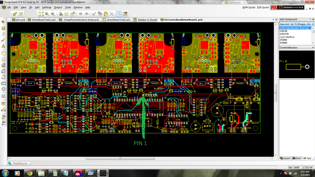
The PICKIT3 has a triangle pointing at pin 1 (mclear):

There is also a dot on the board to show pin 1:
 |
|
|
|
|
The Following User Says Thank You to MPaulHolmes For This Useful Post:
|
|
|
03-06-2015, 05:14 PM
|
#1748 (permalink)
|
|
Master EcoModder
Join Date: Sep 2010
Location: Saskatoon, canada
Posts: 1,488
Thanks: 746
Thanked 565 Times in 447 Posts
|
YippeeeeEEE!!! The PICkit 3 arrived late yesterday
Quote:
Originally Posted by MPaulHolmes
The PICKIT3 has a triangle pointing at pin 1 (mclear):
|
Yup - found that.
Quote:
|
There is also a dot on the board to show pin 1:
|
Yup - found that too.
Connect it up, start up the MPLAB X software, load up the hex file.
No joy .. error message about no connection
turn all of it off and disconnect. Plug it all back in and wiggle the controller-to-ICSP connection as well as the ICSP to PICkit 3 connection back and forth a bit in case we've had some corrosion sneak in.
Power up - it works!
Program the dsPIC - and it comes back with OK.
Connect up the serial port at 115K,n,8,1 and press enter a few times. No response.
Oh - I still don't know whether TX on the board is FROM the chip or TX from the laptop TO the chip. Try the cable that I made with the TX and RX reversed. Still no joy.
Laptop is running XP SP3. Built-in serial on the docking station (I think I will re-christen it Leviathon! It has a network connection but using any modern anti-virus software would leave no CPU time for doing anything else!)
I was using the built-in serial on the docking station, but I have an older (10 years?) USB-to-serial converter as well as a new-this-year usb-to-serial converter to try out.
But my mind was fuzzy, so I went to bed. Will continue this evening.
What does the controller put out to say "I'm alive"? Will a few Carriage returns get me a prompt? |
|
|
|
|
03-06-2015, 07:50 PM
|
#1749 (permalink)
|
|
PaulH
Join Date: Feb 2008
Location: Maricopa, AZ (sort of. Actually outside of town)
Posts: 3,832
Thanks: 1,362
Thanked 1,202 Times in 765 Posts
|
It may have to be erased before programming. I'm not sure though. It's a hex file that was made in mplab 8.83. I would guess that it shouldn't matter if it's programmed on mplab x though. If you hit enter, it should show a message about the version. "AC controller version 0.1" or something.
Last edited by MPaulHolmes; 03-06-2015 at 10:17 PM..
|
|
|
|
|
03-07-2015, 01:02 AM
|
#1750 (permalink)
|
|
Master EcoModder
Join Date: Sep 2010
Location: Saskatoon, canada
Posts: 1,488
Thanks: 746
Thanked 565 Times in 447 Posts
|
Quote:
Originally Posted by MPaulHolmes
It may have to be erased before programming. I'm not sure though.
|
I think I had the 'erase before programming' checkbox checked .. but I'll do the explicit erase, then reprogram. That's step 1.
Quote:
|
It's a hex file that was made in mplab 8.83. I would guess that it shouldn't matter if it's programmed on mplab x though.
|
I found 8.83 in the mplab archive and downloaded the zip file. If the erase does not help, I'll try using 8.83. That's step 2. Do you have the version of the compiler you are using? (just in case that makes a difference somewhere down the line) Are there versions for the libraries?
Quote:
|
If you hit enter, it should show a message about the version. "AC controller version 0.1" or something.
|
So it waits for "enter" first. Good. I should not miss it if hyperterminal doesn't connect right away.
I pushed down the 3 pin connector, on the serial cable I built, onto the control board, harder and got one of the cables 'sort of' working. If I hit enter, some gibberish shows up on the screen. I tried Enter a few times, then changed speed. Perhaps it was coincidence, but I made it down to 9600 baud, n, 8, 1 and it began to echo my characters .. or most of them. The high bit was set on one or two characters (not consistent) so there were line-drawing characters mixed in. I tried changing parity but no joy there.
So I tried JUST 115,200 baud. After a couple of dozen tries at ENTER (with some squares as a response from the control board) the cursor returns to the beginning of the line. Typing in 'config' does not display anything on the terminal. But 'config' echoes. At that point, everything echoes but nothing else happens. But there are no parity errors or goofy characters echoed either.
I took my second cable (with tx and rx backward) and re-soldered it to match the first cable. The second cable is much shorter so maybe it will have less trouble? Not so far. The second cable does not work at all. I knew my soldering skills were RUSTY ... but I expected things to at least WORK.
Step 3 will be to use a USB to serial adapter, first cable then second cable.
I'll report back tomorrow.
|
|
|
|
|


