Go Back   EcoModder Forum > EcoModding > Fossil Fuel Free > Open ReVolt: open source DC motor controller
Register Now
 Register Now
 

Reply  Post New Thread
 
Submit Tools LinkBack Thread Tools
Old 10-30-2009, 06:14 PM   #2521 (permalink)
EcoModding Apprentice
 
Join Date: May 2009
Location: Australia
Posts: 109
Thanks: 0
Thanked 2 Times in 2 Posts
Quote:
Originally Posted by MPaulHolmes View Post
Hey Ben! Basically, you have to *somehow* solder on the little 3 pronged thing. It's going to be a tight fit getting a soldering iron in there. You could insert the 3 pronged thing, then heat the metal legs of the 3 prongs, and then melt the solder that way?
Soldering tips 101.
1. It is very very important that both the surfaces to be connected are raised to the temperature that will melt the solder, this ensures a proper join.
2. You should limit the time the components are hot, particularly the pad on a PCB as heat will degrade the glue that holds the pad to the substrate.

  Reply With Quote
Alt Today
Popular topics

Other popular topics in this forum...

   
Old 10-30-2009, 08:15 PM   #2522 (permalink)
Joe
 
Join Date: Feb 2009
Location: phx
Posts: 260
Thanks: 0
Thanked 48 Times in 38 Posts
Quote:
Originally Posted by MPaulHolmes View Post
Hey Ben! Basically, you have to *somehow* solder on the little 3 pronged thing. It's going to be a tight fit getting a soldering iron in there. You could insert the 3 pronged thing, then heat the metal legs of the 3 prongs, and then melt the solder that way?
the male serial connector needs to be soldered to the control board? eek, that seems like a daunting task if you can't easily access the bottom of the board.

Maybe you can get a small iron in there to heat both the pad and the pin without removing the board. You can try heating from the top, feeding solder from the bottom, and try to use the molten solder to heat the pad, but I've tried similar things with mosfet legs without luck. maybe put the controller upside down so that gravity is on your side.

If you end up needing to remove the board to get to the underside, the two heavy guage wires make it a pain in the butt (I had to do it in order to add the little diodes). If you can heat em both at the same time, shouldn't be too hard to remove. Otherwise, you'll eventually get it off by heating each individually and going back and forth.

Once you get those out (assuming you've removed the nuts too), the board will rotate up while still connected by the gate resistors. Now you have access to the bottom and can solder away.

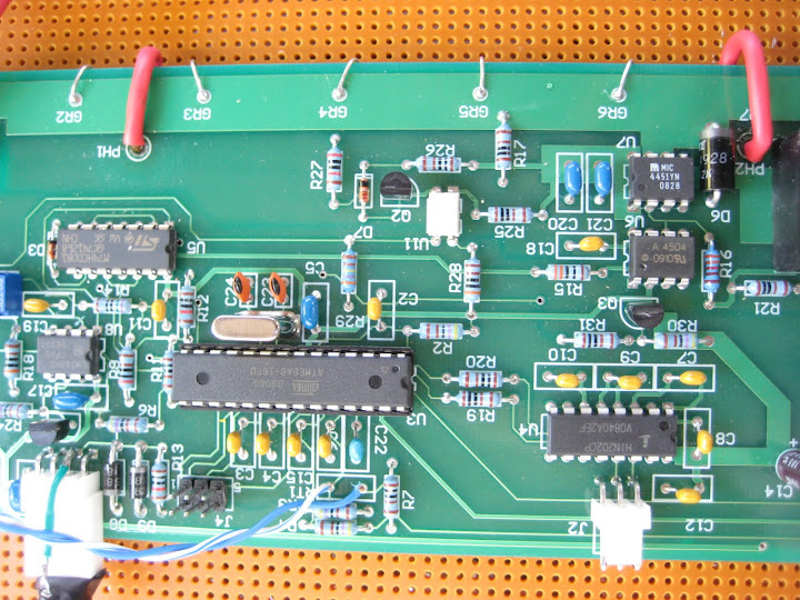
Now, the problem becomes soldering those two heavy guage wires once you're done. I had trouble fitting them back through the board with the old solder clogging it up. Additionally, I screwed up the pads because it took a lot of heat to get those wires out of there. So, I did the work-around as shown in the picture below.

I trimmed the heavy guage wire down so it wouldn't hit the board. Then, soldered the red wire to it while the board was rotated away and covered with electrical tape. Then, I was able to solder the other end of the red wire to the control board while having access to the bottom of the board. I now know I have a good solder joint and am able to rotate the board back down and secure down with the nuts.

hopefully you don't have to do that, but just in case you (or anyone else) really really have to access the bottom of the board, this is an option.

__________________
ReVolt AZ testing thread:

http://ecomodder.com/forum/showthrea...ting-9325.html
  Reply With Quote
Old 10-30-2009, 08:21 PM   #2523 (permalink)
PaulH
 
MPaulHolmes's Avatar
 
Join Date: Feb 2008
Location: Maricopa, AZ (sort of. Actually outside of town)
Posts: 3,832

Michael's Electric Beetle - '71 Volkswagen Superbeetle 500000
Thanks: 1,368
Thanked 1,202 Times in 765 Posts
Ben, just heat the metal prongs and apply the solder. It will wick right through the holes. Don't worry.

On a side note, I am trying a charger sort of. I'm aiming for maybe 8 amps at whatever voltage. I just ordered a LEM 50, which is basically identical to the LEM 300. I'm going to wrap about 8-10 turns of wire through it, so that it will measure current in the range of 0amp to 10amp or so.

I soldered a full wave bridge rectifier to a piece of pcb, and then added a couple 270uF 400v Ripple Caps. I then soldered an electrical Plug thing to the rectifier, and plugged it in, and I got about 160v, which was approximately constant.

I'm just wondering how constant it stays under load. I was going to buy a few different power resistors and see if it got more ripply. I guess that it wouldn't at relatively low power. Then I was going to just hook up a populated control board, and a power section with a single pair of capacitors, a mosfet, and a freewheel diode. I ordered a 300v 160amp 19mOhm RdsOn mosfet, and a 600volt 80amp freewheel diode. I think the controller can act as a charger.
__________________
kits and boards

Last edited by MPaulHolmes; 10-31-2009 at 04:13 AM..
  Reply With Quote
Old 10-31-2009, 04:52 PM   #2524 (permalink)
EcoModding Lurker
 
Join Date: Aug 2009
Location: texas
Posts: 10
Thanks: 0
Thanked 0 Times in 0 Posts
paul
your assemble manual looks good here is one that you might take like as a pattern for newbees
http://www.kostyun.com/PDF/building_mighty_mini.pdf
mike
  Reply With Quote
Old 11-01-2009, 04:18 AM   #2525 (permalink)
Master EcoModder
 
jackbauer's Avatar
 
Join Date: Sep 2009
Location: Ireland
Posts: 734
Thanks: 26
Thanked 304 Times in 171 Posts
You'll need some way to monitor the voltage. The controller only monitors current. Great idea though. I'll be the first beta tester
  Reply With Quote
Old 11-01-2009, 11:22 AM   #2526 (permalink)
PaulH
 
MPaulHolmes's Avatar
 
Join Date: Feb 2008
Location: Maricopa, AZ (sort of. Actually outside of town)
Posts: 3,832

Michael's Electric Beetle - '71 Volkswagen Superbeetle 500000
Thanks: 1,368
Thanked 1,202 Times in 765 Posts
My friend that did the layout is mailing me a circuit for measuring pack voltage. By the way, I love your picture, Jack!
__________________
kits and boards
  Reply With Quote
Old 11-01-2009, 04:29 PM   #2527 (permalink)
Master EcoModder
 
jackbauer's Avatar
 
Join Date: Sep 2009
Location: Ireland
Posts: 734
Thanks: 26
Thanked 304 Times in 171 Posts
Well then i guess we'll need a new thread for the charger . In all seriousness i'm very interested as its the next big expense after motor and controller. Are you looking at an rpm input to the controller at all? I'm going to modify the orange led part of the circuit to drive an opto and hook that to the alternator warning light on the car's dash. Easy to see that the controller is happy. Might be an option worth designing in for a future pcb as a sort of "health" output.
  Reply With Quote
Old 11-01-2009, 05:44 PM   #2528 (permalink)
PaulH
 
MPaulHolmes's Avatar
 
Join Date: Feb 2008
Location: Maricopa, AZ (sort of. Actually outside of town)
Posts: 3,832

Michael's Electric Beetle - '71 Volkswagen Superbeetle 500000
Thanks: 1,368
Thanked 1,202 Times in 765 Posts
Joe already has a thread for his charger! haha. I was reading it and getting ideas. His is much higher power though. I was aiming for maybe 8-10amp, 0-144v or so.
__________________
kits and boards
  Reply With Quote
Old 11-01-2009, 06:15 PM   #2529 (permalink)
EcoModding Lurker
 
Join Date: Jul 2009
Location: Vallejo,CA
Posts: 43

49state 4door - '91 Geo Metro 4 door
90 day: 59.31 mpg (US)

old blue - '91 Geo Metro base CA
Thanks: 2
Thanked 4 Times in 4 Posts
Paul, the optoisolator used with the shunt would also work well to isolate your voltage measurement. A 1000:1 divider with a 68 ohm output resistance would give a 200 volt full scale. You might have to put a C across the 68K part of the divider, just like tuning a scope probe. There is a spare isolator in the package with the third version of the shunt. This one uses brass closet bolts instead of salvaged starter solenoid bolts, so more can be made.
  Reply With Quote
Old 11-01-2009, 06:20 PM   #2530 (permalink)
PaulH
 
MPaulHolmes's Avatar
 
Join Date: Feb 2008
Location: Maricopa, AZ (sort of. Actually outside of town)
Posts: 3,832

Michael's Electric Beetle - '71 Volkswagen Superbeetle 500000
Thanks: 1,368
Thanked 1,202 Times in 765 Posts
Yes! Bob!!! It got here on Friday. Thank you!!!!! That's a good idea.

__________________
kits and boards
  Reply With Quote
Reply  Post New Thread


Similar Threads
Thread Thread Starter Forum Replies Last Post
Paul and Sabrina's Cheap 3 Phase Inverter (AC Controller) with Field Oriented Control MPaulHolmes Fossil Fuel Free 3480 05-04-2022 05:43 PM
Paul & Sabrina's Cheap EV Conversion MPaulHolmes Fossil Fuel Free 542 11-12-2016 09:09 PM
Three Dirt Cheap DIY Electric Cars - Part 5 SVOboy EcoModder Blog Discussion 0 12-12-2008 04:10 PM


Powered by vBulletin® Version 3.8.11
Copyright ©2000 - 2024, vBulletin Solutions Inc.
Content Relevant URLs by vBSEO 3.5.2
All content copyright EcoModder.com