 01-17-2012, 09:34 AM
|
#5441 (permalink)
|
|
EV test pilot
Join Date: Jan 2008
Location: Oconomowoc, WI, USA
Posts: 4,435
Thanks: 17
Thanked 663 Times in 388 Posts
|
I am all for making sure RTD Explorer and the Open ReVolt continue to get along well.
I am NOT an electronics guy, and running RTD Explorer on my salvaged tablet is the only way I have to get inside the mind of the controller!
|
|
|

|
 Today Today
|
|
|
|
 Other popular topics in this forum...
|
|
|
|
|
01-17-2012, 10:20 AM
|
#5442 (permalink)
|
|
EcoModder Student
Join Date: Nov 2008
Location: Youngsville, NC
Posts: 117
Thanks: 11
Thanked 14 Times in 13 Posts
|
Way too many years of experience dictates that this is a bad idea. RTD can be made to "test" the controller to determine it's version or capability. Then switch to an appropriate "new" set of functions as opposed to the "original" set.
Many methods can be used, but maintaining multiple sets of software is a real PITA and prone to errors.
Also, as mentioned by Adam, the help function should not be in the controller. There is a limited amount of data space available (unless you are willing to add external flash and perhaps a file system). The RTD has almost unlimited space to maintain a help function. Most limited space microcontroller environments would provide, as their help function, a simple list of available commands, short and sweet.
Thanks to all for perfecting this amazing set of open source projects.
Eric
Quote:
Originally Posted by sawickm

Would you have to make it compatible with the old controllers?
Why couldn't it just be an enhancement for the new controllers? The old ReVolt controllers use the older version of RTD, and the new ReVolt controllers Yours and Paul’s use the updated RTD?
Users would just have to buy the new controllers to get the updated features?
-Mark  |
__________________
1995 BMW 318i EV in the making
|
|
|
|
|
The Following User Says Thank You to esoneson For This Useful Post:
|
|
|
01-17-2012, 11:37 AM
|
#5443 (permalink)
|
|
PaulH
Join Date: Feb 2008
Location: Maricopa, AZ (sort of. Actually outside of town)
Posts: 3,832
Thanks: 1,362
Thanked 1,202 Times in 765 Posts
|
Don't think that everything's finalized on my end! haha. Programming changes are the easiest thing in the world. I just hate confusing names. About once every 3 days someone emails me asking what everything means, and how to use it, and etc... What's the usage... It would be nice for it to be as simple and clean as possible on just a standard serial display, as well as with RTD explorer. lots of people who email me just want to use a basic text display like Realterm. I always send them a help file, but then when they are actually using it, they forget.
Right now the names are things like
c-rr 4
throttle-min-rc 342
throttle-max-rc 876
pc-time 45
save
it would be nice for it to be
current-ramp-rate 4
full-throttle 342
zero-throttle 876
precharge-time 45
save
Here's an example of the help:
help precharge-time
precharge-time is how long you want for the capacitors to charge through the precharge resistor.
Ex: precharge-time 57
Note: The time is in tenths of a second.
Also, if you hit enter, it would be nice if the config variable names are displayed in exactly the same way that you type them. Not c-rr for the command and current_ramp_rate for config. I never remember the "config" command to see the variables.
All the help text used about 15% of the space on the atmega168, so it's up to about 70% full. The text was saved in the program space rather than the data space. I bet the bootloader would have to change in order to use the 328 instead.
If everyone used RTD-Exporer it would be helpful, but it would be nice if the serial display on its own was more user friendly.
|
|
|
|
|
01-17-2012, 12:38 PM
|
#5444 (permalink)
|
|
EcoModding Lurker
Join Date: Mar 2009
Location: Ohio
Posts: 16
Thanks: 8
Thanked 15 Times in 6 Posts
|
I've finished working the bugs out of my 500 amp controller. I use a 4D systems LCD screen with touch to monitor and change controller setting. It's really easy to program and with the new Visi IDE it's easy to make good looking displays.
I also wrote a simple data-logging program that displays and records all the controller information then save it to an xls file. I just open it in Excel and I can create all the graphs I want. It was really helpful while tune my PD control values.
I also added a 4 line "normal LCD screen to the case of the controller. It was helpful for debugging, but is kind of useless while driving. It is nice to have when I'm showing off my setup to friends.
I've also modified the controller to use WarP Hall Effect throttle shown here. http://www.evsource.com/tls_throttle.php
Thanks Paul for starting this endeavor, and every one that's helped make it better.
Last edited by Camaro; 01-17-2012 at 09:07 PM..
|
|
|
|
|
The Following 2 Users Say Thank You to Camaro For This Useful Post:
|
|
|
01-17-2012, 03:43 PM
|
#5445 (permalink)
|
|
ReVolt Enthusiast
Join Date: Jun 2009
Location: Michigan, USA
Posts: 239
Thanks: 97
Thanked 47 Times in 40 Posts
|
Quote:
Originally Posted by MPaulHolmes
About once every 3 days someone emails me asking what everything means, and how to use it, and etc... I always send them a help file, but then when they are actually using it, they forget.
|
Hi Paul,
I don't know if this would help you, but the Ecomodder Admins could create a "Open ReVolt Help/FAQs" sticky thread for the top of the forum page ???
If your interested send me your help file and any info you would want to place in that help file.
Or I could post this wiki doc file https://www.onlinefilefolder.com/1sjc9rcEg4FisL
-Mark
Last edited by sawickm; 01-17-2012 at 04:02 PM..
|
|
|
|
|
The Following User Says Thank You to sawickm For This Useful Post:
|
|
|
01-18-2012, 03:29 AM
|
#5446 (permalink)
|
|
PaulH
Join Date: Feb 2008
Location: Maricopa, AZ (sort of. Actually outside of town)
Posts: 3,832
Thanks: 1,362
Thanked 1,202 Times in 765 Posts
|
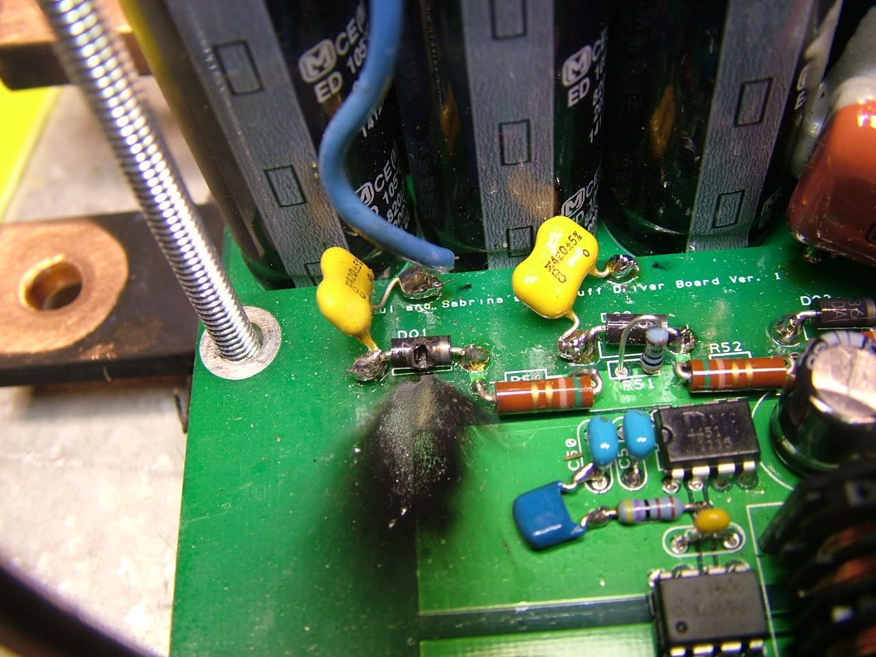
Controller destruction photos:
ALL of the Transient voltage supression diodes had failed shorted. No picking on me with the soldering. This stupid board had some parts assembled and dissassembled like 4 friggen times.:
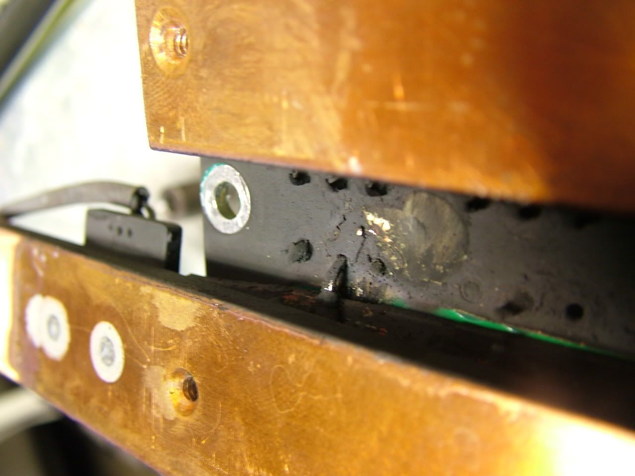
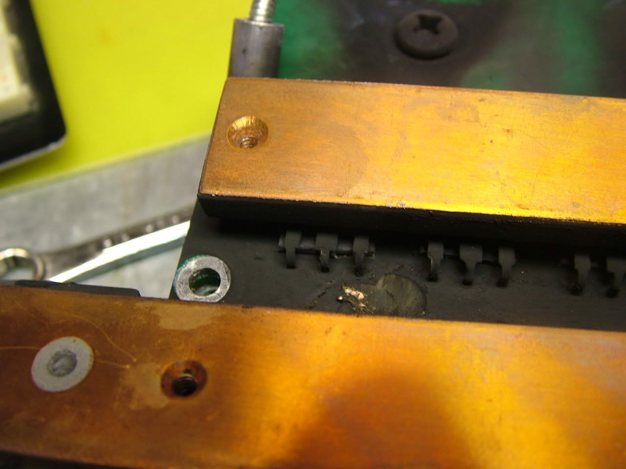
gate and source legs blown off of ALL the mosfets. Most drain legs still there. Probably because the leg is attached to the copper back of the mosfet:
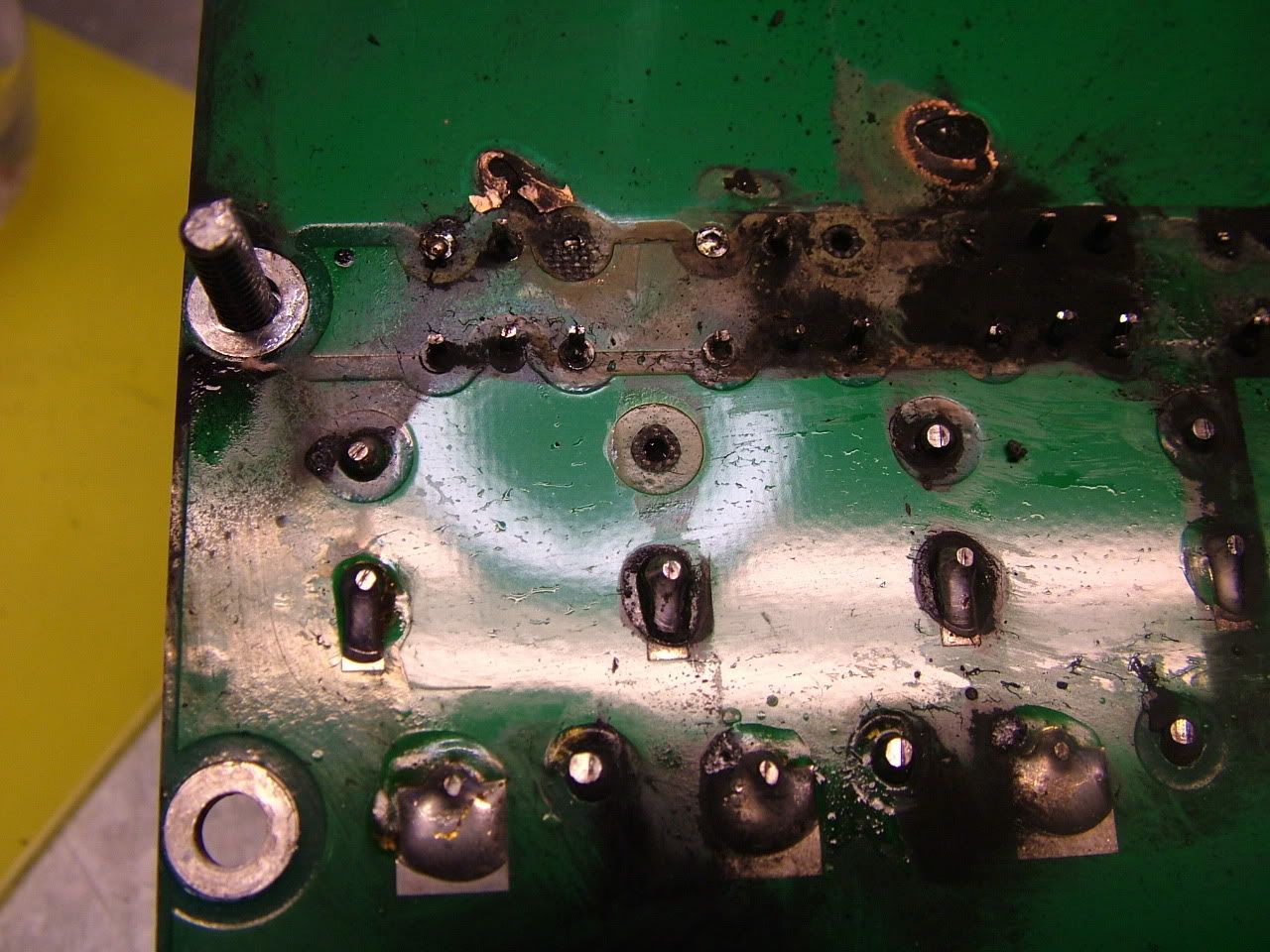
The diodes are friggen gangster.:
2 capacitors had ONE of their pads vaporised. But the capacitor was still good. Don't ask me how that happened. haha:
I think the TVS diodes failed because the gate signal was too noisy, so the TVS diodes had to conduct too much and overheated and failed and maybe caused the mosfets to fail. I have no idea really, but why on earth would all the TVS diodes fail short circuited? If the source was moving at all relative to gate, the TVS diode could have conducted forward too, and that could have really overheated things.
Hey! I just read a paper on diode failure analysis:
1. Small-step cross-sectioning technique in combination with electrical probing, light emission microscopy, liquid crystal technique, and chemical staining was successfully used to reveal damage in the failed metallurgically bonded diodes.
2. In all cases damage to the diodes was caused by local overheating above the melting temperature of silicon.
They also studied TVS diode failure specifically. They overheated and failed short circuit. I guess that gate signal needs to get cleaned up. haha. Hopefully the new driver board works well for that. If not, it's off to "High Side Driver". Hey! My ex-brother in law was often a high side driver. Well, whenever he drove, he was high. |
|
|
|
|
01-18-2012, 09:24 AM
|
#5447 (permalink)
|
|
EcoModding Apprentice
Join Date: Nov 2010
Location: Annapolis
Posts: 159
Thanks: 0
Thanked 32 Times in 27 Posts
|
We've had failures like that.
The cause was the MOSFETs shorting the gate to the drain during failure, applying pack voltage to the gate driver circuit. The underlying cause was counterfeit IR MOSFET from a Chinese supplier, which had far higher on resistance than they were supposed to have. Our previous MOSFETs failed shorted, or ejecting the bond wires out of the package top (explosively) but usually leaving the gate insulated. These destroyed something on the gate driver board every time they failed.
Your root cause might still be a noisy gate signal causing overheating (we had issues with staccato turn-on cycling when using optocouplers), but the TVS explosion probably occurred after the MOSFETs failed.
We figured out during prototyping that putting a TVS on the gate driver output (vs. on the MOSFET side of the gate resistor) would result in the gate driver resistor acting like a fuse, often saving the gate driver and reducing the rebuild time.
|
|
|
|
|
The Following 2 Users Say Thank You to DJBecker For This Useful Post:
|
|
|
01-19-2012, 04:35 PM
|
#5448 (permalink)
|
|
PaulH
Join Date: Feb 2008
Location: Maricopa, AZ (sort of. Actually outside of town)
Posts: 3,832
Thanks: 1,362
Thanked 1,202 Times in 765 Posts
|
Fran had observed similar oscillation to what I had going on with a brushless DC motor he had done a couple years ago. He think's it's too hard of gate drive. Next time around I'm going to use either 15 Ohm or 22 Ohm or something like that The source at the driver and the source at the inside of the mosfet had a difference of probably a few volts. V = dI/dt*L. The L is pretty small, but the dI/dt was friggen ginormous. If I slow down dI/dt some, V is going to get smaller and it will keep the mosfet from going on/off/on/off.
Some igbts don't have this problem because of the Kelvin emitter connection, which has a separate path to the emitter inside the igbt from the power path.
|
|
|
|
|
01-19-2012, 05:14 PM
|
#5449 (permalink)
|
|
EcoModding Apprentice
Join Date: Nov 2010
Location: Annapolis
Posts: 159
Thanks: 0
Thanked 32 Times in 27 Posts
|
Quote:
Originally Posted by MPaulHolmes
Some igbts don't have this problem because of the Kelvin emitter connection, which has a separate path to the emitter inside the igbt from the power path.
|
IGBTs also avoid turn-off ringing because they don't (can't) turn off quickly. You have to wait for the minority carriers to decay (recombine) before the device is fully off. This absorbs some of the inductive energy that would otherwise "slosh" around the cables, capacitors and controller structure.
There is a lot of design effort around turning off IGBTs. You can't get rid of the tail end of the minority carrier recombination, but you can immediately stop generation of new carriers by a negative gate voltage, and bypassing the gate resistor with a diode.
MOSFETs don't have same issue and are relatively easy to turn off.
We have (had) a turn-off ringing issue which we "fixed" by using 39 ohm gate resistors. That costs us a little in the turn-on speed, but it's easier to change resistors and add cooling than building a better capacitor board or physically reducing the current loop area in our controller. |
|
|
|
|
01-20-2012, 11:06 PM
|
#5450 (permalink)
|
|
EcoModding Lurker
Join Date: Oct 2009
Location: North Carolina
Posts: 41
Thanks: 23
Thanked 8 Times in 4 Posts
|
Hey Paul,
Sent you a payment through PayPal, but later received a returned email
message stating that a permanent error had occurred (mailbox is full) and
the email had not been sent. Just wanted to let you know and to also see
if you actually received the funds.
Sorry to post here, but I don't have enough posts to send a private message yet.
Jim Brock
|
|
|
|
|


