 11-23-2015, 10:21 PM
|
#2361 (permalink)
|
|
Master EcoModder
Join Date: Sep 2010
Location: Saskatoon, canada
Posts: 1,488
Thanks: 746
Thanked 565 Times in 447 Posts
|
Quote:
Originally Posted by MPaulHolmes

I've been updating the software more, so that all the optional variables are in the normal nice format, like real life actual amps (with 1 decimal) and real life volts, and also % of voltage being used, etc.. 16 variables to choose from (0, 1, 2, ..., or all 16). And as you suggested, the 1kHz timer is one of the 16, so you can know what time things are actually happening. I should get it tested and sent over to you hopefully tomorrow. And when you mentioned the csv format or whatever it was called, I looked that up, and just changed it so the output format would be CSV.
|
Cool. That will make it faster to import to LibreOffice Calc - the open source version of excel 
Quote:
No sense forcing people to cut and paste into excel. Here's the list of variables:
Code:
	// bit 15 set: display counter1ms
	// Bit 15 set: display Id
	// bit 14 set: display Iq
	// Bit 13 set: display IdRef
	// bit 12 set: display IqRef
	// Bit 11 set: display Vd
	// bit 10 set: display Vq
	// Bit 9 set: display Ia
	// bit 8 set: display Ib
	// bit 7 set: display Ic
	// Bit 6 set: display Va
	// bit 5 set: display Vb
	// bit 4 set: display Vc
	// Bit 3 set: display rawThrottle
	// bit 2 set: display normalizedThrottle
	// Bit 1 set: display temperature
	// bit 0 set: display slipSpeedRPM
	// Bit  3 set: display electricalSpeedRPM
	// bit  2 set: display mechanicalSpeedRPM
	// Bit  1 set: display batteryCurrent
	// bit  0 set: display % of voltage being used.  Ratio of radius of <Vd,Vq> to Total voltage.
|
So - more than 16 means you can do 32 and have some spare slots for future expansion!
I would suggest this split - no real reason but it seems to work out.
Code:
        // LogFlags1
	// Bit 15 set: display Id
	// bit 14 set: display Iq
	// Bit 13 set: display IdRef
	// bit 12 set: display IqRef
	// Bit 11 set: display Vd
	// bit 10 set: display Vq
	// Bit 9 set: display Ia
	// bit 8 set: display Ib
	// bit 7 set: display Ic
	// Bit 6 set: display Va
	// bit 5 set: display Vb
	// bit 4 set: display Vc
        // bits 3 - 0 are for future

        // LogFlags2
	// bit 15 set: display counter1ms
	// Bit 14 set: display rawThrottle
	// bit 13 set: display normalizedThrottle
	// Bit 12 set: display temperature
	// bit 11 set: display slipSpeedRPM
	// Bit 10 set: display electricalSpeedRPM
	// bit  9 set: display mechanicalSpeedRPM
	// Bit  8 set: display batteryCurrent
	// bit  7 set: display % of voltage being used.  Ratio of radius of <Vd,Vq> to Total voltage.
        // bits 6 - 0 are for future
Looking forward to the new code!
|
|
|

|
|
The Following User Says Thank You to thingstodo For This Useful Post:
|
|
 Today Today
|
|
|
|
 Other popular topics in this forum...
|
|
|
|
|
11-23-2015, 10:35 PM
|
#2362 (permalink)
|
|
PaulH
Join Date: Feb 2008
Location: Maricopa, AZ (sort of. Actually outside of town)
Posts: 3,832
Thanks: 1,362
Thanked 1,202 Times in 765 Posts
|
That looks like a good way to split it up. I'll do that. I was thinking more about the boosting. Here's my attempt to figure out the boost current requirement without simulation, just so I can get my head wrapped around it. Let's say we are doubling the DC voltage:
DC Power from batteries = Vbatt * Ibatt
DC Power from the capacitor bank to the 3 phase inverter = Vcaps * Icaps =
2*Vbatt * 0.5*Ibatt
Now, the power to the 3 phase inverter is
PowerInverter = 1.5 * Vcaps * IphasePeak (I always use this one. it's my favorite format)
So, 1.5 * Vcaps * IphasePeak = Vcaps * Icaps. So,
1.5*IphasePeak = Icaps.
So, 1.5*IphasePeak = 0.5*Ibatt
So, 3*IphasePeak = Ibatt.
|
|
|
|
|
The Following 2 Users Say Thank You to MPaulHolmes For This Useful Post:
|
|
|
11-23-2015, 10:35 PM
|
#2363 (permalink)
|
|
Master EcoModder
Join Date: Sep 2010
Location: Saskatoon, canada
Posts: 1,488
Thanks: 746
Thanked 565 Times in 447 Posts
|
Update for Nov 23
I bought a multi-turn pot for accurate throttle on the AC controller - so the throttle should work for the next test - likely Wednesday or Friday - just a small bit of soldering required.
Lighting for the meters: they are hard to read. Some lighting is required, and I'm going to try moving them to where they don't vibrate (not on the motor base).
A quick test with a couple of LED flashlights seemed to work OK. The angle is important so the camera can read the numbers. Maybe a cardboard stand to hold things in place so the phone and lighting stay where they need to be?
There WILL BE DUCT TAPE! |
|
|
|
|
The Following User Says Thank You to thingstodo For This Useful Post:
|
|
|
11-24-2015, 02:08 AM
|
#2364 (permalink)
|
|
Permanent Apprentice
Join Date: Jul 2010
Location: norcal oosae
Posts: 523
Thanks: 351
Thanked 318 Times in 215 Posts
|
Quote:
Originally Posted by MPaulHolmes
As for the boosting, where is the 3x current coming from? I have 2 intended uses in mind for the super cheapo AC TO-247 controller with boosting. First, I just wanted to allow higher RPM under load. I have a 200amp 300uH inductor, and my simulations seemed to show that things stay under relative control in that situation. There is a ton of capacitance (to keep things cheap, I am using a bunch of 450v electrolytic caps. heck it worked for the 500amp controller), which I hope will allow for a dual use as a solar MPPT/ 3 phase grid tie. And if you don't want to go to jail, you could instead use it as a MPPT/ 3 phase "not grid tie" sort of thing. I bet there are people who would want 3 phase power at their house, and who have maybe 12 lead acid batteries laying around. Well, maybe there aren't but I'm going to pretend that.
|
Ok - I want one of those.  I could power my lathe & mill with my solar system
I've done some calcs about boost converter design using some TI app notes, and the numbers work out very well. In a nutshell:
Input voltage minimum: 468V (144 Leaf cells in series at a minimum 3.25V)
Output voltage: 650V
Output current: 115A ( 75kW - obviously 50kW or whatever would be lower )
boost duty cycle: 33.75%
switching frequency 10kHz (also worked out for 25kHz)
inductance: 273uH ( running @ 25kHz, it's 109uH )
Max switch current: 202A (well under the maximum of 300A )
Output ripple voltage: 13V ( 2% of the 650V bus )
Output Capacitance 298uF ( running @ 25kHz, it's 119uF) Both available from SBE.
Using a low inductance bus an a ultra-low ESR capacitor, the ripple due to the capacitor is completely negligible.
In fact, a 200A, 300uH inductor would be almost perfect. Do you have any specs on it?
Also, do you know if the DSPIC 6010A/6015 will run the PWM with two different switching frequencies? It might be best to run the booster at a higher frequency than the inverter, depending on the switches used.
- E*clipse |
|
|
|
|
11-24-2015, 02:42 AM
|
#2365 (permalink)
|
|
Permanent Apprentice
Join Date: Jul 2010
Location: norcal oosae
Posts: 523
Thanks: 351
Thanked 318 Times in 215 Posts
|
Quote:
Originally Posted by MPaulHolmes
That looks like a good way to split it up. I'll do that. I was thinking more about the boosting. Here's my attempt to figure out the boost current requirement without simulation, just so I can get my head wrapped around it. Let's say we are doubling the DC voltage:
DC Power from batteries = Vbatt * Ibatt
DC Power from the capacitor bank to the 3 phase inverter = Vcaps * Icaps =
2*Vbatt * 0.5*Ibatt
Now, the power to the 3 phase inverter is
PowerInverter = 1.5 * Vcaps * IphasePeak (I always use this one. it's my favorite format)
So, 1.5 * Vcaps * IphasePeak = Vcaps * Icaps. So,
1.5*IphasePeak = Icaps.
So, 1.5*IphasePeak = 0.5*Ibatt
So, 3*IphasePeak = Ibatt.
|
Ok, so let's say we have a 75kW inverter and Vcaps = 650V
75kW = 1.5 * 650V * IphasePeak
IphasePeak = 76.9A Great! NBD for 3 TO-247 switches.
So what I was advocating was to run the battery voltage closer to the bus voltage. In the example I worked out, Vbatmin = 144 cells * 3.25V (below that, there's not much power available anyway)
Vbatmin = 468V or 468V/650V = 0.72
Using your last equation:
1.5*IphasePeak = 0.5*Ibatt >>>changes slightly >>> 1.5*IphasePeak = 0.72*Ibatt
so,
2.08*IphasePeak = Ibatt
Given IphasePeak = 76.9A for a 75kW inverter,
2.08*76.9A = 160A
The number is a bit lower than the TI app note's maximum switch current of 202A, but two completely different methods produced close results.
- E*clipse |
|
|
|
|
The Following User Says Thank You to e*clipse For This Useful Post:
|
|
|
11-24-2015, 03:30 AM
|
#2366 (permalink)
|
|
PaulH
Join Date: Feb 2008
Location: Maricopa, AZ (sort of. Actually outside of town)
Posts: 3,832
Thanks: 1,362
Thanked 1,202 Times in 765 Posts
|
I'm fairly certain you can only use one switching frequency for all 4 of the duties with the 30f6015 and 30f6010. I think you are right. It would be nice to have the option of a higher frequency for boosting. The 300uH 200amp inductor's part number is ch-200:
http://www.signaltransformer.com/sit.../pdf/CH-CL.pdf
$339 bucks. ouch. haha. But it is awesome. It's been in my MPPT tracker for the last 2.5 years, running 24 hours a day in sometimes 900 degree weather. That is not an exaggeration at all. |
|
|
|
|
The Following User Says Thank You to MPaulHolmes For This Useful Post:
|
|
|
11-24-2015, 06:01 AM
|
#2367 (permalink)
|
|
Master EcoModder
Join Date: Oct 2012
Location: USA
Posts: 1,408
Thanks: 102
Thanked 252 Times in 204 Posts
|
Quote:
Originally Posted by MPaulHolmes
So, 3*IphasePeak = Ibatt.
|
yup, or if you have a 2xboost converter between the battery and the inverter then 3*IphasePeak = Iboost, and ~6*IphasePeak=Ibatt. Basically you need an inverter-sized boost converter switch, and it wouldn't surprise me if ultimately you need a motor sized inductor (frequency/size tricks aside). Power in=power out.
It seems a fine strategy for stationary applications, but even your ch-200-nd weighs 50lbs, which is the same as about 3kwh of batteries, plus the boost circuit adds losses. Matching the battery voltage/amperage and motor voltage/amperage is a much better strategy in an ev IMHO.
Last edited by P-hack; 11-24-2015 at 06:54 AM..
|
|
|
|
|
11-24-2015, 09:09 AM
|
#2368 (permalink)
|
|
Master EcoModder
Join Date: Sep 2010
Location: Saskatoon, canada
Posts: 1,488
Thanks: 746
Thanked 565 Times in 447 Posts
|
Sorry - so many posts I didn't see this one yesterday.
Quote:
Originally Posted by MPaulHolmes
thingstodo, that is very cool! Do you know if it works on the evil horrible "it's going in the garbage soon" iphone? haha.
|
My wife has an Iphone 4s and I have installed gmail on it (to get to the link on google hangouts) and installed google hangouts but I have not had a chance to test it as yet. Maybe I'll use her phone to video one set of meters in the next video.
Quote:
|
That's the one I have been cursed with. I like how it shows 2 pictures, and also your voice is very easy to hear. It really didn't pick up the noise.
|
As long as you keep adding cameras/phones you can get up to 10 pictures ... I NEVER thought I'd be low on that sort of hardware for a project!
I got a new bluetooth headset. My 3-year old headset lasts just under 45 minutes ... and I have a one hour teleconference each week so I had to upgrade. I *REALLY* like it. You can't tell the motors are even running!
Quote:
|
You know, I have my very first prototype DC controller (maybe it was my 2nd). It used a heavy duty copper heat spreader. It would need a control board mounted to it. Since your controller failed, to get it to work again, you might have to replace the ten 22Ohm gate resistors (they sometimes crack when there has been a failure)
|
The resistors look fine. They don't get hot. And it's a bit weird that the controller will take 12V and pack voltage ... and no problems so far. I need to put a motor on as well and make sure there still IS A PROBLEM ... after all, I did cut off 2 transistors before I started measuring stuff ...
Quote:
|
and replace the MIC4451. And possibly the hcpl4504 with a new hcpl4506. Everything else should be OK.
|
So .. would that be the equivalent of an overhaul for an ICE engine?
Quote:
|
I can send you that controller for you to keep. It should work fine. I've never used it though. What's the cheapest shipping way to you? I don't mind paying for shipping. You are doing so much to help in the development, and I am so "thankful" (thanksgiving shout-out).
|
That would be AWESOME .. USPS is likely the fastest and easiest. Definitely avoid UPS - if their normal delivery performance was as expensive and as poor as their international performance - they would be out of business in 10 days.
I *FINALLY* received parts to build 3 of the IGBT drivers. I ordered the parts from DIGIKEY in August and they arrived the first week in November. I won't be getting the soldering done until I get a new tip for the weller station. My present tip is a bit large.
Quote:
|
As for the boosting, where is the 3x current coming from?
|
Not sure I follow. Did I post a confusing comment?
Quote:
|
I have 2 intended uses in mind for the super cheapo AC TO-247 controller with boosting. First, I just wanted to allow higher RPM under load. I have a 200amp 300uH inductor, and my simulations seemed to show that things stay under relative control in that situation. There is a ton of capacitance (to keep things cheap, I am using a bunch of 450v electrolytic caps. heck it worked for the 500amp controller), which I hope will allow for a dual use as a solar MPPT/ 3 phase grid tie. And if you don't want to go to jail, you could instead use it as a MPPT/ 3 phase "not grid tie" sort of thing. I bet there are people who would want 3 phase power at their house, and who have maybe 12 lead acid batteries laying around. Well, maybe there aren't but I'm going to pretend that.
|
I would like 3 phase power at my house and my cabin. But I've been warned that it is specifically illegal under Canadian Electrical Code. I guess I'll have to do some research!
As for the boost - I have a 100 amp 240V breaker feeding what will be my car charger. My car pack is 16s3p leaf cells for fully-charged open circuit of 128V. If I can get one of the Netgain Industrials fixed, I'll be running 48s1p at 384V. The charger would need boost from 240VAC ... so I'm IN!
Feeding into 3 phase on the grid here would require $$$ of equipment for the grid tie and the location would be at one of the distribution points where the utility drops from 72KV or 138KV long distance distribution to 13,800V local distribution voltage. The utility 'allows' solar to 'grid tie' with $10K of hardware, but that's 240V and they are counting on your neighbors to 'use up' that electricity. If you do any significant (25 KW) generation they claim that it unbalances their 3 phase in the local area. |
|
|
|
|
11-24-2015, 11:38 AM
|
#2369 (permalink)
|
|
PaulH
Join Date: Feb 2008
Location: Maricopa, AZ (sort of. Actually outside of town)
Posts: 3,832
Thanks: 1,362
Thanked 1,202 Times in 765 Posts
|
Quote:
Originally Posted by e*clipse
The number is a bit lower than the TI app note's maximum switch current of 202A, but two completely different methods produced close results.
- E*clipse |
I was forgetting about efficiency. If their current was 202amp, and assuming 100% efficient the input current was 160, I bet the higher current came from the boost losses as well as inverter losses.
Thingstodo, sorry the 3x current boost question was to p-hack. But I just threw it right in as if it was responding to you.
You know, there is also an inductor from them that is 100 amp continuous and is 120uH. That's only 8 pounds and is $128 ($110 in quantity 10). I know the 200amp version was rated for up to 300amp intermittent without the inductance being impacted much (it was not close to saturating at that current). I can't find the stupid graph they sent me now though. I bet the 100amp could do 150amp for short periods.
Here are 3 graphs for what the boosting looks like. The battery amps are blue. The switch is green. Some of it is hidden by the blue. The red is the DC "capacitor current" that is being fed to the inverter.
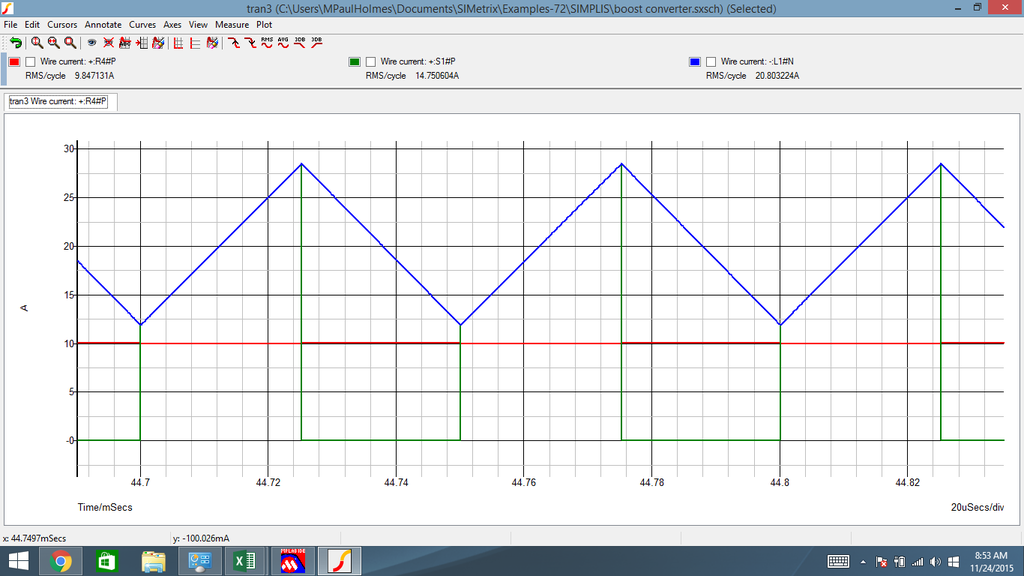
So, from the graph, switch RMS current is around:
Code:
IswitchRMS = (Ibatt + Icaps) / 2
IswitchRMS = (3*IphasePeak + 1.5*IphasePeak)/2
IswitchRMS = 2.25*IphasePeak
IswitchRMS = 3.18*IphaseRMS
And again from the graph,
Code:
IswitchPEAK = 2.8*Icaps
IswitchPEAK = 2.8 * 1.5 * IphasePeak = 4.2 * IphasePeak
IswitchPeak = 4.2 * sqrt(2) * IphaseRMS = 6 * IphaseRMS
|
|
|
|
|
The Following 2 Users Say Thank You to MPaulHolmes For This Useful Post:
|
|
|
11-24-2015, 12:43 PM
|
#2370 (permalink)
|
|
Master EcoModder
Join Date: Oct 2012
Location: USA
Posts: 1,408
Thanks: 102
Thanked 252 Times in 204 Posts
|
Quote:
Originally Posted by MPaulHolmes
...
Here are 3 graphs
|
Yah that is what I'm seeing too, it is like exactly the opposite of zvzc. Though I can't say the bucking inverter switches have it much better, except there are 3x of them to share the load, and they occasionally get a break at zero crossings.
p.s. 70% ripple might be a bit much. the only rule of thumb I have there is 30%. and the inductance value vs frequency matters a lot (as does core material, and etc).
|
|
|
|
|


