Go Back   EcoModder Forum > EcoModding > Fossil Fuel Free > Open ReVolt: open source DC motor controller
Register Now
 Register Now
 

Reply  Post New Thread
 
Submit Tools LinkBack Thread Tools
Old 01-08-2010, 11:24 AM   #2861 (permalink)
PaulH
 
MPaulHolmes's Avatar
 
Join Date: Feb 2008
Location: Maricopa, AZ (sort of. Actually outside of town)
Posts: 3,832

Michael's Electric Beetle - '71 Volkswagen Superbeetle 500000
Thanks: 1,368
Thanked 1,202 Times in 765 Posts
Air cooled. I'm probably 1-2 work days away from ordering pcbs, in a perfect world where I actually had 1-2 days to work on it, and then had the money to order the pcb. haha. This is a picture of the layout with one high side and one low side driver:


I need to change the spacing for the 3 different ground planes, but it's just a rough draft. I need to add 1 more driver to the high side and 1 more to the low side. Synchronous rectification is really really touchy because of the possibility of high and low side being turned on at the same time by accident (even a little glitch I think could short the mosfets). I was thinking of using 4 isolated 12v supplies. One for each driver. Fran was telling me about a different tricky way that simulates isolation using some small inductors and capacitors as the pseudo isolated power supplies, so I might try that instead, but I'm a brute force, totally inelegant sort of guy. haha. (it's true)

__________________
kits and boards
  Reply With Quote
Alt Today
Popular topics

Other popular topics in this forum...

   
Old 01-08-2010, 11:48 AM   #2862 (permalink)
EV test pilot
 
bennelson's Avatar
 
Join Date: Jan 2008
Location: Oconomowoc, WI, USA
Posts: 4,435

Electric Cycle - '81 Kawasaki KZ440
90 day: 334.6 mpg (US)

S10 - '95 Chevy S10
90 day: 30.48 mpg (US)

Electro-Metro - '96 Ben Nelson's "Electro-Metro"
90 day: 129.81 mpg (US)

The Wife's Car - Plug-in Prius - '04 Toyota Prius
90 day: 78.16 mpg (US)
Thanks: 17
Thanked 663 Times in 388 Posts
I have a couple of heatsinks that I pulled off a junkyard forklift battery charger.

They have large fins, but ALSO two holes running the long direction through the base of the heatsink.

These heatsinks could be used for aircooling, but would be a snap for converting to liquid-cooling as well!

If anyone is planning a High-AMP version of the controller, keep an eye for for heatsinks that could potentially be liquid-cooled as well.
__________________


300mpg.org Learn how to BUILD YOUR OWN ELECTRIC CAR CHEAP
My YouTube Videos
  Reply With Quote
Old 01-08-2010, 02:54 PM   #2863 (permalink)
Custom EV Builder...
 
Join Date: Jul 2009
Location: Ohio
Posts: 57
Thanks: 8
Thanked 1 Time in 1 Post
Quote:
Originally Posted by MPaulHolmes View Post
Air cooled. I'm probably 1-2 work days away from ordering pcbs, in a perfect world where I actually had 1-2 days to work on it, and then had the money to order the pcb. haha. This is a picture of the layout with one high side and one low side driver:


I need to change the spacing for the 3 different ground planes, but it's just a rough draft. I need to add 1 more driver to the high side and 1 more to the low side. Synchronous rectification is really really touchy because of the possibility of high and low side being turned on at the same time by accident (even a little glitch I think could short the mosfets). I was thinking of using 4 isolated 12v supplies. One for each driver. Fran was telling me about a different tricky way that simulates isolation using some small inductors and capacitors as the pseudo isolated power supplies, so I might try that instead, but I'm a brute force, totally inelegant sort of guy. haha. (it's true)
Nice work Paul. Adam and I briefly talked about a similar set up but I have zero time. I'm still trying to finish the composite structure for the "Orion". Plus all the projects at home.
  Reply With Quote
Old 01-08-2010, 05:32 PM   #2864 (permalink)
AC-DC enthusiast
 
mrbigh's Avatar
 
Join Date: Nov 2009
Location: Long Island, NY
Posts: 282

Dual-PWR PHEV - '04 Toyota Prius

Kopper - '79 Bradley Bradley GT-II
Thanks: 123
Thanked 54 Times in 37 Posts
Quote:
Originally Posted by MPaulHolmes View Post
I need to add 1 more driver to the high side and 1 more to the low side. Synchronous rectification is really really touchy because of the possibility of high and low side being turned on at the same time by accident (even a little glitch I think could short the mosfets).....
..... I was thinking of using 4 isolated 12v supplies. One for each driver. Fran was telling me about a different tricky way that simulates isolation using some small inductors and capacitors as the pseudo isolated power supplies, so I might try that instead, but I'm a brute force, totally inelegant sort of guy. haha. (it's true)
If I'm not wrong, there are isolated -/+ regulated power supplies modules similar to the ones that are being in use now.
Can you please list the added improvements to this upgraded PCB revision?.

Some suggestions for the "To do List" that would make a great motor controller.

-Would it be implemented any temperature sensor readings, also through its serial port?, like a controller's temperature cut back and an additional motor temperature input sensor, (both in one OP AMP chip circuit) .
-Current sensor reading on DC (battery side) input? End user optional decision and budget.
-Selection of throttle input by resistive and/or hall effect.
__________________
. .. .. . .......
Prius Absolutum Dominium . ..........KOPPER
PHEV conversion since Dec 2006.. . .... .Future EV
. . . . . . . .CALCars # 27. . . . . . . . . . ..on the works now !!
. . . . . . . . . . . . . . . . .. . ........

Last edited by mrbigh; 01-08-2010 at 06:04 PM..
  Reply With Quote
Old 01-09-2010, 04:17 AM   #2865 (permalink)
Master EcoModder
 
jackbauer's Avatar
 
Join Date: Sep 2009
Location: Ireland
Posts: 734
Thanks: 26
Thanked 304 Times in 171 Posts
Positive and negative dc dc converters are readily available. I'm using one in the charger. I'd be looking at putting a serious negative voltage on the gate of the the device your turning off. Just pulling it to ground won't be enough. my 2c.
__________________
Now, Cole, when you shift the gear and that little needle on the ammeter goes into the red and reads 2000 Amps, that's bad.
www.evbmw.com
  Reply With Quote
Old 01-09-2010, 11:14 PM   #2866 (permalink)
Master EcoModder
 
Join Date: Apr 2009
Location: Charlton MA, USA
Posts: 463

EVVette - '71 Chevy Corvette Coupe
Thanks: 31
Thanked 183 Times in 94 Posts
Quote:
Originally Posted by mrbigh View Post
-Current sensor reading on DC (battery side) input? End user optional decision and budget.
As of right now, we are able to compute the battery amps inside the micro controller very accurately. This how we limit the battery amps. In my testing of the battery amps limit testing last week, I was commanding a 20A limit and with my fluke meter, I was showing 21A on the battery terminals. I also set it to 100A limit and then showed 100.5A on the fluke meter!! with both of those, its about 1% error. Not bad for doing it based of motor current!!

So adding an additional current sensor and circuitry needed to measure battery amps when its not really needed would just end up costing about $30 more when the feature is already in place for free.

EDIT: Ive attached a picture of the Fluke meter with the reading. Look at the computer in the background, You can see Battery_Amps_Limit = 100 and the meter says -100.5 because I had it on backwards. LOL. Enjoy!!

-Adam
__________________
www.EVVette.com - 1971 Corvette Coupe Conversion to all Electric!
www.AdamBrunette.com - Machining, CNC, Robotics and Electronics.

You can download RTD Explorer for the Cougar controllers at www.EVVette.com
  Reply With Quote
The Following User Says Thank You to adamj12b For This Useful Post:
deodeo (03-22-2012)
Old 01-09-2010, 11:39 PM   #2867 (permalink)
AC-DC enthusiast
 
mrbigh's Avatar
 
Join Date: Nov 2009
Location: Long Island, NY
Posts: 282

Dual-PWR PHEV - '04 Toyota Prius

Kopper - '79 Bradley Bradley GT-II
Thanks: 123
Thanked 54 Times in 37 Posts
Quote:
Originally Posted by adamj12b View Post
As of right now, we are able to compute the battery amps inside the micro controller very accurately. This how we limit the battery amps. In my testing of the battery amps limit testing last week, I was commanding a 20A limit and with my fluke meter, I was showing 21A on the battery terminals. I also set it to 100A limit and then showed 100.5A on the fluke meter!! with both of those, its about 1% error. Not bad for doing it based of motor current!!

So adding an additional current sensor and circuitry needed to measure battery amps when its not really needed would just end up costing about $30 more when the feature is already in place for free.
Great!!!!
One wish of the "TO DO LIST" is granted with all the hardware built in Paul''s controller and Adam's tinkering with out extra expenses.
__________________
. .. .. . .......
Prius Absolutum Dominium . ..........KOPPER
PHEV conversion since Dec 2006.. . .... .Future EV
. . . . . . . .CALCars # 27. . . . . . . . . . ..on the works now !!
. . . . . . . . . . . . . . . . .. . ........
  Reply With Quote
Old 01-12-2010, 01:04 PM   #2868 (permalink)
Joe
 
Join Date: Feb 2009
Location: phx
Posts: 260
Thanks: 0
Thanked 48 Times in 38 Posts
Data and Charts!

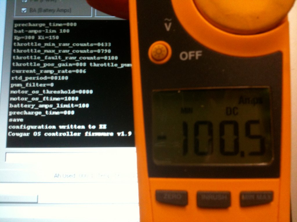
I took a trip to a store the other day and recorded both the 'to' and 'from' legs of the trip. I was mostly curious what the temperature readings and the Ah calculations (I haven't yet had an instrument to measure consumed Ah), but I thought that everyone might find the motor/battery amps interesting as well. These are the readouts from the serial output from the controller.

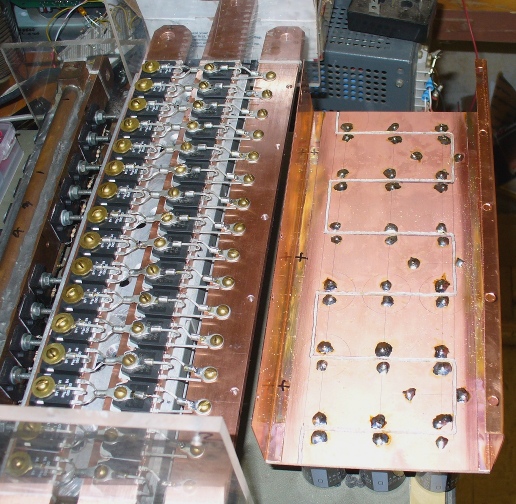
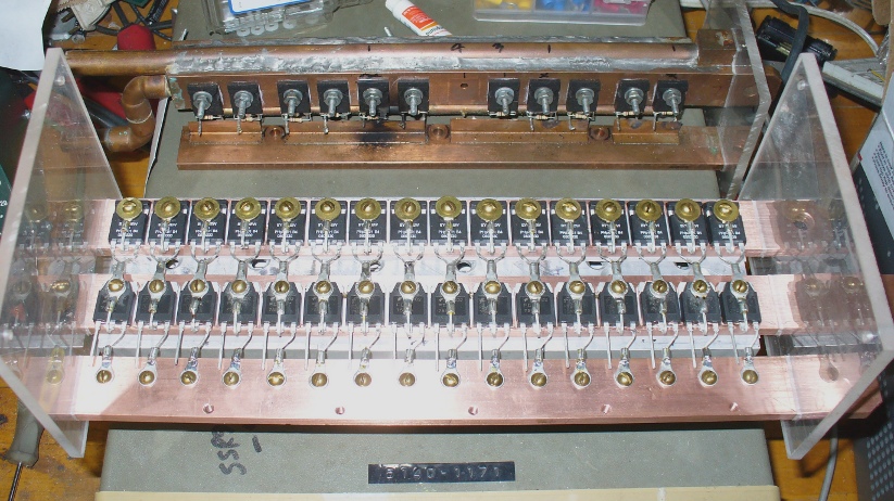
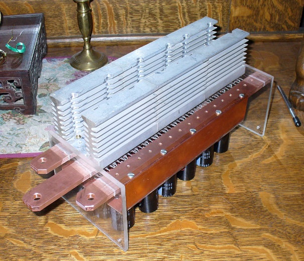
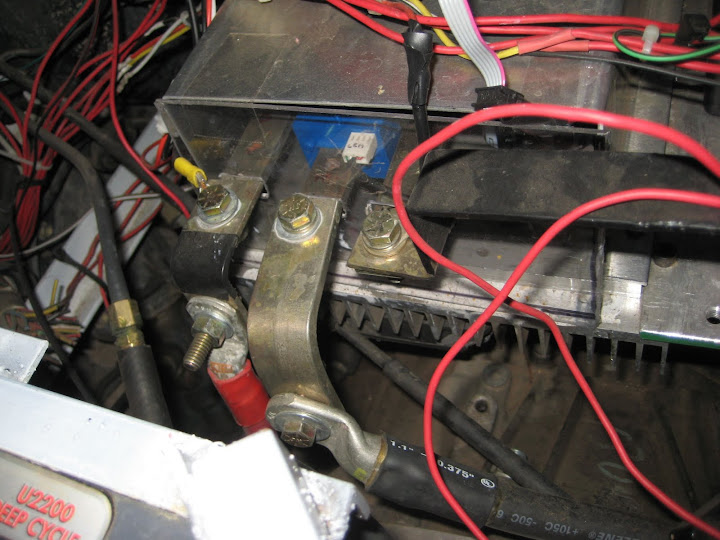
(Reminder: I'm running an impulse 9 with a 144v pack. Vehicle weight is about 3800 lb, and below is my heatsinking: Also, I have a copper heat spreader...)


Here's the 'To' leg. Everything is plotted vs. time. The jagged lines are the motor and battery amps and are referenced to the axis on the left. Both Ah and Temp are plotted on the right axis since they were in about the same range.


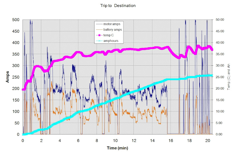
The trip above consisted of several miles of city driving, abut 10 miles of highway (at 55 mph, 3rd gear, about 5200 rpm), and another mile or so of city driving. Looking at the motor/battery amps, you can see the high amp accelerations from a standstill in the beginning and end, and also the lesser demanding (200 motor amps average) cruise on the highway in the middle .

Some observations:

The car sat in the shade beforehand so I think the initial temperature is a good indication of ambient (about 20C). The temperature rises pretty quick during the high amp accelerations while 'city' driving. Temps continue to rise gradually and I think they level off right at the end of the trip. This 'leveling off' is more apparent when looking at the return trip since the controller and heatsink start out already warm (see below).

Just before 16 min, I'm stuck at the offramp stoplight for over a minute. You can see the temperature fall quickly during that time.

This is the return trip along roughly the same route (a different city route at the end):


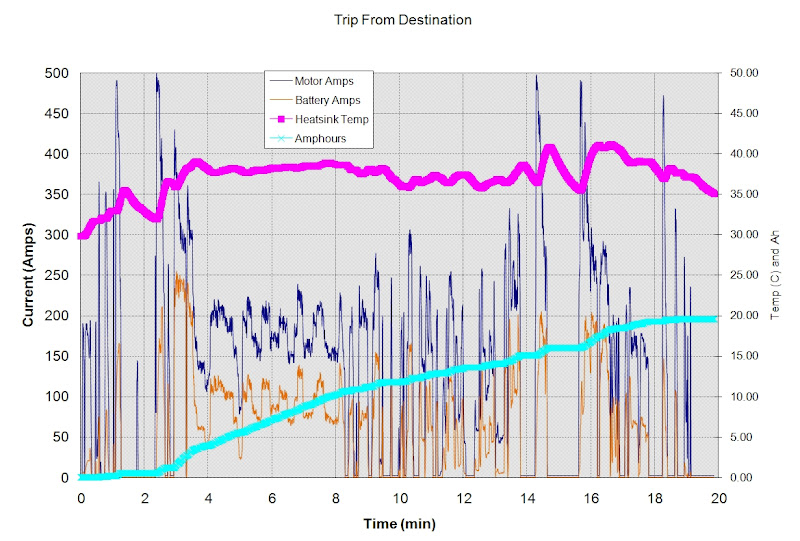
The acceleration onto the highway happens between minutes 3 and 4 where the battery amps rise to almost 250amps. The oscillations in motor amps from minutes 4-8 are from the freeway underpasses. At minute 8, i get stuck in some construction traffic and the driving is slower (40mph) and a little more erratic. The slight change in the slope of the Ah curve from these two sections shows the lower power requirement when driving slower.

The temp starts out at 30degC since it didnt' get a chance to cool down. Once it gets going though, it seems to level out pretty quickly around 38C, though the erratic driving kinda screws it up. Even so, after driving for 40 mins total, the high amp draws at the end causes peak temps just over 40C.

Thus, with this style driving, peak temps on the heat spreader seem to be about 20C over ambient. If thermal cutback doesn't come on until 75C, that should allow for operation in 55C ambient temperatures (which is ridiculously hot), or more strenuous operation in lower temperatures.

Also... this 27 mi trip consumed 45.3 Ah which is about 1.68 Ah/mi. Assuming an average battery voltage of 139V, that gives about 230 Wh/mi. I do pretty good on the freeway, but the heavy car eats amps in stop and go.

Paul, feel free to use these charts on your site if you want to. I vaguely remember someone asking about recorded runs to look at performance. I can share the raw data too...
__________________
ReVolt AZ testing thread:

http://ecomodder.com/forum/showthrea...ting-9325.html
  Reply With Quote
The Following 2 Users Say Thank You to jyanof For This Useful Post:
MPaulHolmes (01-12-2010), mpgmike (01-14-2022)
Old 01-16-2010, 07:27 PM   #2869 (permalink)
EvEagle
 
Join Date: Apr 2009
Location: Lansing, MI
Posts: 40
Thanks: 0
Thanked 7 Times in 4 Posts
Paul, I just wanted to show you yet another configuration for the power section. The mosfets are only rated at 75 amps, 280 volts, which is why there are so many of them; but at $1.35 each, I thought I would give it a try. One advantage of this configuration is that there are no thermal pads under the diodes or the mosfets, and I have 20 square inches of contact with the heat sinks.
  Reply With Quote
The Following 2 Users Say Thank You to edown For This Useful Post:
deodeo (03-22-2012), mpgmike (01-14-2022)
Old 01-16-2010, 07:35 PM   #2870 (permalink)
EvEagle
 
Join Date: Apr 2009
Location: Lansing, MI
Posts: 40
Thanks: 0
Thanked 7 Times in 4 Posts
The bottom side.

  Reply With Quote
The Following 2 Users Say Thank You to edown For This Useful Post:
deodeo (03-22-2012), mpgmike (01-14-2022)
Reply  Post New Thread


Thread Tools


Similar Threads
Thread Thread Starter Forum Replies Last Post
Paul and Sabrina's Cheap 3 Phase Inverter (AC Controller) with Field Oriented Control MPaulHolmes Fossil Fuel Free 3480 05-04-2022 05:43 PM
Paul & Sabrina's Cheap EV Conversion MPaulHolmes Fossil Fuel Free 542 11-12-2016 09:09 PM
Three Dirt Cheap DIY Electric Cars - Part 5 SVOboy EcoModder Blog Discussion 0 12-12-2008 04:10 PM


Powered by vBulletin® Version 3.8.11
Copyright ©2000 - 2024, vBulletin Solutions Inc.
Content Relevant URLs by vBSEO 3.5.2
All content copyright EcoModder.com