 02-21-2010, 10:43 AM
|
#2981 (permalink)
|
|
EV test pilot
Join Date: Jan 2008
Location: Oconomowoc, WI, USA
Posts: 4,435
Thanks: 17
Thanked 663 Times in 388 Posts
|
I added the coffee cups and stickers to the Open ReVolt store.
I like the idea of a sticker for the case. That is actually something I wanted to do from sometime back.
|
|
|

|
 Today Today
|
|
|
|
 Other popular topics in this forum...
|
|
|
|
 02-21-2010, 11:38 AM
|
#2982 (permalink)
|
|
EcoModding Lurker
Join Date: Sep 2009
Location: Western NY
Posts: 27
Thanks: 5
Thanked 1 Time in 1 Post
|
Thanks Ben for getting those up there.
Yes Jack I would have done that. I've always thought the controller should have something on it. I'll buy some and send to Paul to include in new kits.
Joihn
|
|
|

|
|
The Following User Says Thank You to E Vdubya For This Useful Post:
|
|
 02-21-2010, 01:10 PM
|
#2983 (permalink)
|
|
Joe
Join Date: Feb 2009
Location: phx
Posts: 260
Thanks: 0
Thanked 48 Times in 38 Posts
|
Quote:
Originally Posted by jackbauer

Had a thought (I know I know!). One of the big concerns with a dc controller is a short circuit failure in the power section leading to a runaway motor or vehicle.
|
Another option is to have the main contactor open and close with the accelerator pedal. Press the pedal, cantactor closes, release and contactor opens. The advantage is that the user's first instinct is to release the accelerator if something bad happens which would cause the disconnection of the battery pack.
Disadvantages are numerous. The contactor gets a lot of cycles, can be very noisy, and if not timed correctly, the controller can start providing power before the contactor closes. when this happens, the caps drain to zero volts and then get whammed with pack voltage when the contactor closes. bad for caps, contactor contacts, and would probably cause jerky starts. But, all of these disadvantages can be accommodated.
The controller can still be have 'master' contactor control and disallow the contactor to close before a specific time allows.
Just something to consider... |
|
|

|
|
The Following User Says Thank You to jyanof For This Useful Post:
|
|
 02-21-2010, 06:05 PM
|
#2984 (permalink)
|
|
PaulH
Join Date: Feb 2008
Location: Maricopa, AZ (sort of. Actually outside of town)
Posts: 3,832
Thanks: 1,362
Thanked 1,202 Times in 765 Posts
|
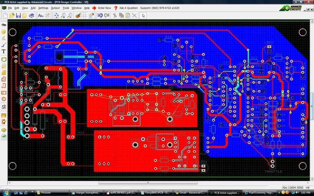
These are really good ideas! Hey, want to see something cool? I finally sent in a through-hole prototype of the Syncronous rectification controller to Advanced Circuits. Also, the big beefcake 230amp 200v mosfets (24 of them) arrived!

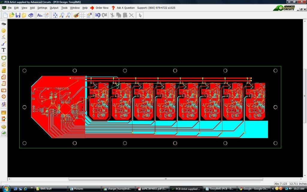
Also, I finally finished the dang BMS layout. I have tested it almost completely, and it's ready to be sent to Advanced Circuits too:

I figured,there's never a good time to send it in. I'm sure there are some minor mistakes (with the controller), but there ain't nothing like actually making something to fix what's wrong. I ordered 5 of the boards. The next version will probably be surface mount, once I get the bugs worked out. 1000amp here we come! ya! The bms is surface mount, and I like the idea of having a company do the soldering for me.
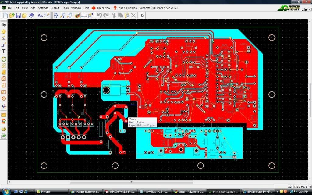
OH ya, also the control board for the 6kW charger is ready to be sent in too. hehe. There are a couple things I'm going to change with it, so it can talk with the bms. 
Last edited by MPaulHolmes; 02-21-2010 at 06:19 PM..
|
|
|

|
|
The Following 2 Users Say Thank You to MPaulHolmes For This Useful Post:
|
|
 02-21-2010, 08:55 PM
|
#2985 (permalink)
|
|
AC-DC enthusiast
Join Date: Nov 2009
Location: Long Island, NY
Posts: 282
Thanks: 123
Thanked 54 Times in 37 Posts
|
Paul, it seems that you had been very busy.
Congrats in you PCBs accomplishments 
__________________
. .. .. . .... . .... ... ...
Prius Absolutum Dominium . ..........KOPPER
PHEV conversion since Dec 2006.. . .... .Future EV
. . . . . . . .CALCars # 27. . . . . . . . . . ..on the works now !!
. . . . . . . . . . . . . . . . .. . ........
|
|
|

|
 02-22-2010, 02:10 AM
|
#2986 (permalink)
|
|
PaulH
Join Date: Feb 2008
Location: Maricopa, AZ (sort of. Actually outside of town)
Posts: 3,832
Thanks: 1,362
Thanked 1,202 Times in 765 Posts
|
Found beta tester for 1000amp controller!
I found someone that was willing to try the 1000 amp controller! Here's a profile picture of him. Danger is his middle name:
 |
|
|

|
 02-22-2010, 09:14 AM
|
#2987 (permalink)
|
|
ReVolt Enthusiast
Join Date: Jun 2009
Location: Michigan, USA
Posts: 239
Thanks: 97
Thanked 47 Times in 40 Posts
|
Open Source ???
Quote:
Originally Posted by MPaulHolmes

I finally sent in a through-hole prototype of the Syncronous rectification controller to Advanced Circuits.
Also, I finally finished the dang BMS layout. I have tested it almost completely, and it's ready to be sent to Advanced Circuits too.
The next version will probably be surface mount, once I get the bugs worked out. 1000amp here we come!
OH ya, also the control board for the 6kW charger is ready to be sent in too.
|
Hi Paul,
Congratulations with your success on those new projects.
Question, are the new Synchronous rectification controller, BMS, and 6kW Charger your personal projects or are they going to be shared “open source” projects? I have not seen any hardware (Schematics) or software development on those projects shared in this forum.
Is the revision “C” Cougar Controller the last version of “open source” controller to be openly shared with this forum?
Thanks again to you and all the others in this forum for all your hard and successful work !!!
-Mark 
Last edited by sawickm; 02-22-2010 at 10:19 AM..
|
|
|

|
 02-22-2010, 12:49 PM
|
#2988 (permalink)
|
|
Master EcoModder
Join Date: Sep 2009
Location: Ireland
Posts: 734
Thanks: 26
Thanked 304 Times in 171 Posts
|
Forgive my ignorance and skepticism but what benefits are offered by the sync rectification controller? My fear would be the ol' both transistors on at the same time scenario! I can just see my odyssey batteries salavating at the prospect of pumping 2000amps into a short circuit 
By the way if the fish is busy i can help with the beta tests!
__________________
Now, Cole, when you shift the gear and that little needle on the ammeter goes into the red and reads 2000 Amps, that's bad.
www.evbmw.com
|
|
|

|
 02-22-2010, 02:48 PM
|
#2989 (permalink)
|
|
PaulH
Join Date: Feb 2008
Location: Maricopa, AZ (sort of. Actually outside of town)
Posts: 3,832
Thanks: 1,362
Thanked 1,202 Times in 765 Posts
|
Hi Sawickm, the problem with the bms schematic is that it got way out of sync with my layout, and my crappy software won't let me update my schematic from the layout. I'd be happy to post it later. There's also the software, which I'm still working on, but sure! The charger is nothing special. It's just a buck converter with an 80amp rated chassis mount mosfet (I might try for a 50kHz switching speed). I'd be happy to post that too. I'm still working on changing it though (to a dspic30f4011 chip) so it will have a serial interface and CAN interface (like the BRUSA chargers). Right now, with the dspic30f4012 it only has a CAN interface. So that stuff is coming, don't worry. (same with SR controller).
Yo Jack! If there was a short circuit, it would be super bad, so it's really really really touchy. The dsPICs have 6 pwm channels. There's PWM1H, PWM1L, PWM2H, PWM2L, PWM3H, PWM3L. They can be configured as all running independently, or in complementary mode, so that (for example) PWM1H and PWM1L are complements of each other, with the added bonus that you can program the amount of dead-time so that PWM1L and PWM1H are NEVER EVER EVER EVER EVER on at the same time. The beauty of it is, if you want to be really conservative, the only bad thing is that the mosfet body diode will conduct longer. If you want to be all wild and crazy, the dead time can be made as small as possible to minimize heat generated. Here's the benefit:
A body diode has an aproximately fixed voltage drop of around 1v or something. The mosfet has a fixed ON resistance of 0.0075 Ohm (yes,they are that good. hehe)! So, let's say you are doing gentle town driving, and are using 100amps at 144v. Well, that's 10 amps per mosfet/"freewheel mosfet" pair, and the most that the freewheel mosfet could see is at 50% duty, which would be 5 amps (I think that's right). So, the voltage drop of this new fancy "freewheel mosfet" would be 0.0375v. Oh heck ya. Better than 1v.
Now, that was the conservative case. What about doing 1000 amps?! The voltage drop under the worst case across the freewheel mosfet will be 0.375v, which is still better than those stupid diodes! hahaha.
The 3rd and final benefit is, there are no diodes out there that are rated for 230amp and cost $6 new in modest bulk. The legs on these suckers are rated for 160 amp according to the data sheet. Also, their package can dissipate 1600 watts of heat I think (according to the datasheet).
Real life will of course be worse than this, but whatever it's all good! hehe. The dsPICs are designed for just this sort of thing (and also for 3 phase AC drives and such) where high and low side transistors being on at the same time would be catastrophic, so it should be good! I can't wait to find out.
|
|
|

|
|
The Following User Says Thank You to MPaulHolmes For This Useful Post:
|
|
 02-22-2010, 04:31 PM
|
#2990 (permalink)
|
|
EcoModding Lurker
Join Date: Nov 2009
Location: Long Island, NY
Posts: 83
Thanks: 0
Thanked 9 Times in 9 Posts
|
Paul: I designed a 6 KW charger. 120/240 volt, PFC, ISOLATED. Let me know if you want the design. The ferrite inductor design and power transformer design you might find interesting. It's open source. Do you want to start a charger thread? The output is for 45 cells of LiFePo4. 121-165 volts, with optional control pin by a BMS
|
|
|

|
|