03-20-2014, 04:42 PM
|
#6341 (permalink)
|
|
PaulH
Join Date: Feb 2008
Location: Maricopa, AZ (sort of. Actually outside of town)
Posts: 3,832
Thanks: 1,362
Thanked 1,202 Times in 765 Posts
|
routing done! It's going to be a 4 layer board, which can reduce noise by a factor of 10. I'm using layer 2 for the control ground, since all the paths are on the top surface, which makes for an itsy bitsy loop area. I've changed a lot. I'm taking the EVTech list's advice for this one. No experimental correction of turn-on times. I'm just going to match the parts as best I can, and then monitor the current going through each igbt individually, which each igbt hooked up to its own hardware overcurrent protection. There's also desaturation detection, but just for all 3 as a single big IGBT, rather than 3 separate desat detection circuits.
It's just a single control board/driver board that will plug into the 3 IGBTs with female spade connectors that are soldered directly to the control board. There's one PWM signal that goes right to the gate of each IGBT, at which time there's a buffer circuit that can do 15 amps per IGBT.
It also has capacitors right at the gate to emitter, so that the loop area is way smaller than I've ever had it. Also, there are back to back zeners right at each gate to emitter spade connector. If it blows up, then I'll just go home and cry, because it's the best I can do. haha.
Oh heck ya! The UPS truck is coming!
|
|
|

|
|
The Following 2 Users Say Thank You to MPaulHolmes For This Useful Post:
|
|
 Today Today
|
|
|
|
 Other popular topics in this forum...
|
|
|
|
|
03-20-2014, 04:50 PM
|
#6342 (permalink)
|
|
EcoModding Apprentice
Join Date: Feb 2010
Location: Northern Wisconsin
Posts: 137
Thanks: 32
Thanked 39 Times in 23 Posts
|
This sounds great !! 
Dave
__________________
Dave  ...
|
|
|
|
|
The Following User Says Thank You to dave koller For This Useful Post:
|
|
|
03-20-2014, 06:16 PM
|
#6343 (permalink)
|
|
PLUGnGO
Join Date: Sep 2012
Location: Olympia Wa
Posts: 137
Thanks: 75
Thanked 82 Times in 54 Posts
|
Thanks for your hard work Paul - I am really looking forward to putting one of these in my truck.
What are you thinking of for a user interface? Will it be something similar to RTD Explorer? Will we have control of things like max current, low voltage cutback, ramp rate?
A dash mountable LCD to display amps, %PWM, trouble codes, etc. would be nice but probably add a lot of complexity. Maybe a comm port to support a future display?
Last edited by jedsmd; 03-20-2014 at 09:33 PM..
|
|
|
|
|
03-21-2014, 02:20 PM
|
#6344 (permalink)
|
|
PaulH
Join Date: Feb 2008
Location: Maricopa, AZ (sort of. Actually outside of town)
Posts: 3,832
Thanks: 1,362
Thanked 1,202 Times in 765 Posts
|
The code isn't set in stone yet. It's not monitoring voltage on this board, so low voltage cutback wouldn't be an option. It should be good from 0v to 400v at bursts over 1000amp I'm hoping (which would make low voltage cutback a bit complex. Like what batteries are being used, programming nominal voltage, How long should it be allowed to sag down, etc.... If you all really want voltage monitoring, I could include it. I was just trying to keep things simple (and cheaper) at the moment. I could easily spend 6 months on features.
What I had in mind was a basic board that just ran the igbts to get the details of that worked out. Programming max motor amps and current ramp rate wouldn't be a big deal. It also has a relay for controlling the precharge relay coil, and a relay for controlling the main contactor coil (each coil can be up to 10 amps). I was just going to include a basic serial port like before, and send a stream of data. If it conforms to the RTD stream, it could use that.
Last edited by MPaulHolmes; 03-21-2014 at 02:41 PM..
|
|
|
|
|
03-21-2014, 03:26 PM
|
#6345 (permalink)
|
|
PLUGnGO
Join Date: Sep 2012
Location: Olympia Wa
Posts: 137
Thanks: 75
Thanked 82 Times in 54 Posts
|
Quote:
Originally Posted by MPaulHolmes

The code isn't set in stone yet. It's not monitoring voltage on this board, so low voltage cutback wouldn't be an option. It should be good from 0v to 400v at bursts over 1000amp I'm hoping (which would make low voltage cutback a bit complex. Like what batteries are being used, programming nominal voltage, How long should it be allowed to sag down, etc.... If you all really want voltage monitoring, I could include it. I was just trying to keep things simple (and cheaper) at the moment. I could easily spend 6 months on features.
|
I was thinking of the low voltage cutback to protect the batteries. If the batteries sag my BMS will sound the alarm anyway. I don't feel strongly about low voltage cutback - not worth a lot of extra work.
Quote:
|
What I had in mind was a basic board that just ran the igbts to get the details of that worked out. Programming max motor amps and current ramp rate wouldn't be a big deal.
|
I plan to test this unit in a daily driver. I would like to be able to set full throttle around 1000 amps and also have enough control on the low end to smoothly parallel park (An economy/power switch wouldn't be a bad thing).
I don't want to cause extra work but I feel there has to be enough end user control to allow people to tweak to their individual vehicles and driving styles.
Quote:
|
I was just going to include a basic serial port like before, and send a stream of data. If it conforms to the RTD stream, it could use that.
|
Yep that would be great. |
|
|
|
|
The Following User Says Thank You to jedsmd For This Useful Post:
|
|
|
03-21-2014, 05:23 PM
|
#6346 (permalink)
|
|
PaulH
Join Date: Feb 2008
Location: Maricopa, AZ (sort of. Actually outside of town)
Posts: 3,832
Thanks: 1,362
Thanked 1,202 Times in 765 Posts
|
One concern I have with a switch going to the controller is exposing the control voltages to the car's environment. Maybe I could add a cheap optocoupler like the FOD817, and your external switch could switch a 12v or whatever signal, which will toggle a economy/performance port. I'll add that. It will be an extra $0.28 though. haha.
|
|
|
|
|
The Following 2 Users Say Thank You to MPaulHolmes For This Useful Post:
|
|
|
03-21-2014, 07:14 PM
|
#6347 (permalink)
|
|
EcoModding Apprentice
Join Date: Oct 2010
Location: southland NZ
Posts: 153
Thanks: 38
Thanked 86 Times in 55 Posts
|
I would like to be able to set full throttle around 1000 amps and also have enough control on the low end to smoothly parallel park (An economy/power switch wouldn't be a bad thing).
I don't want to cause extra work but I feel there has to be enough end user control to allow people to tweak to their individual vehicles and driving styles.
I'm a mechanical guy so tell me if I'm wrong
I had intended to do that by adding an additional resister in parallel with my throttle
Zero - 5k = Zero to 1000amps
Adding another 5k in parallel I get
Zero - 2.5K = zero to 500amps
You could even have several resister selected by switches
|
|
|
|
|
The Following 2 Users Say Thank You to duncan For This Useful Post:
|
|
|
03-21-2014, 09:28 PM
|
#6348 (permalink)
|
|
PaulH
Join Date: Feb 2008
Location: Maricopa, AZ (sort of. Actually outside of town)
Posts: 3,832
Thanks: 1,362
Thanked 1,202 Times in 765 Posts
|
Well heck, that's tricky. It wouldn't use any power either. That's a nice clever solution. I'll leave the change in there though. It might be nice to have a valet mode, where you could program the valet max current (or teenager mode, but make sure you hide the switch. haha)
|
|
|
|
|
03-22-2014, 08:19 PM
|
#6349 (permalink)
|
|
PaulH
Join Date: Feb 2008
Location: Maricopa, AZ (sort of. Actually outside of town)
Posts: 3,832
Thanks: 1,362
Thanked 1,202 Times in 765 Posts
|
I just sent in the board a couple hours ago:
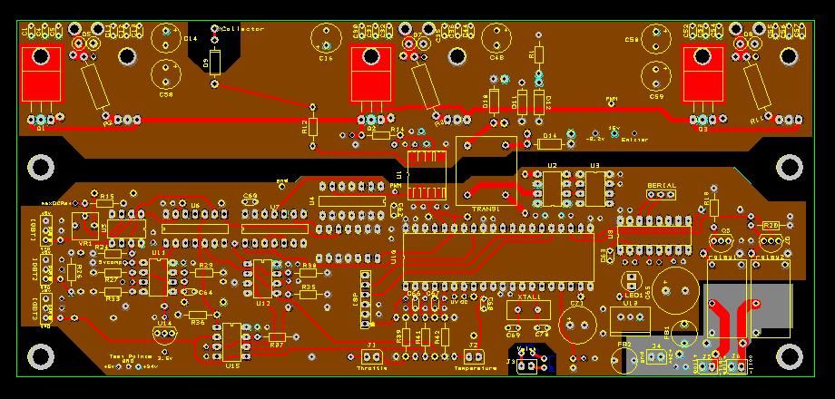
Just one surface mount part. Parts are mounted on the top and bottom. |
|
|
|
|
03-22-2014, 09:50 PM
|
#6350 (permalink)
|
|
PLUGnGO
Join Date: Sep 2012
Location: Olympia Wa
Posts: 137
Thanks: 75
Thanked 82 Times in 54 Posts
|
Looks too clean - is there another layer of traces I'm not seeing, or is it just the red traces and power and ground planes?
Last edited by jedsmd; 03-22-2014 at 10:08 PM..
|
|
|
|
|